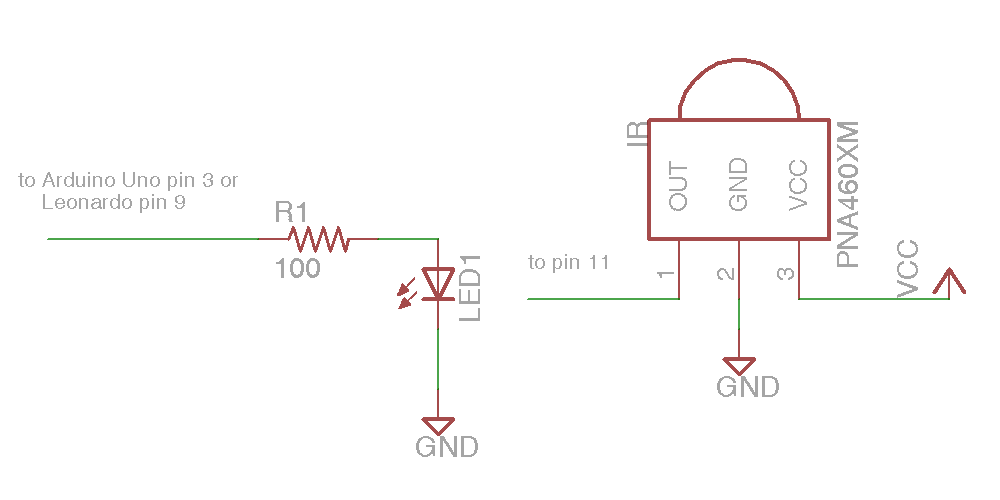
I’ve shared some videos on here talking about my infrared remote control that I built using Arduino Uno so that I could operate my TV and other devices with dozens of functions using only for pushbuttons. The device relies on a tiny circuit that has an infrared LED, a transistor, a resistor, an infrared receiver. The one that I’ve been using was thrown together on a little piece of perf-board that looks like this.
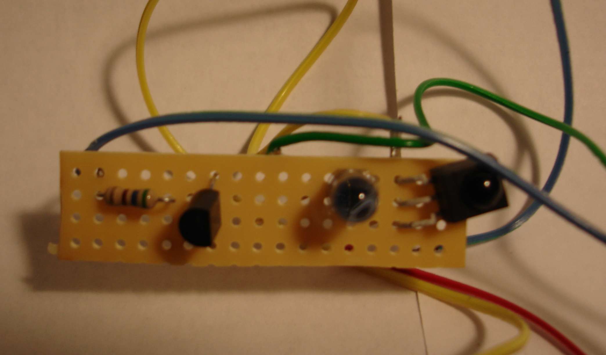
Homemade IR Transceiver Module
However sometimes the unit isn’t pointed in exactly the right direction the signal doesn’t get through. I needed something that was wider angle and perhaps more powerful. They make IR LEDs in either narrow angle or wide-angle versions. Perhaps if I had one of each or even to have each I would get the power I needed. There’s little gadget called a TV-B-Gone that is a battery-powered device with four IR LEDs and a pushbutton. When you push the button it will shut off any TV of any brand. People use it as a joke to walk into a place like a sports bar, electronic store, fitness center etc. and slyly turn off every TV in the place. I thought if I studied the output portion of the circuitry for that device maybe I could build my own little board that just did the transmitting and add my receiver to it.
Because I don’t know a lot about transistor circuit design I thought I would go to the discussion forums of my favorite parts place adafruit.com where they have an entire forum dedicated to TV-B-Gone and similar devices. They were very helpful in teaching me some basic circuit design skills and in advising me on this project. You can read the discussions here and here.
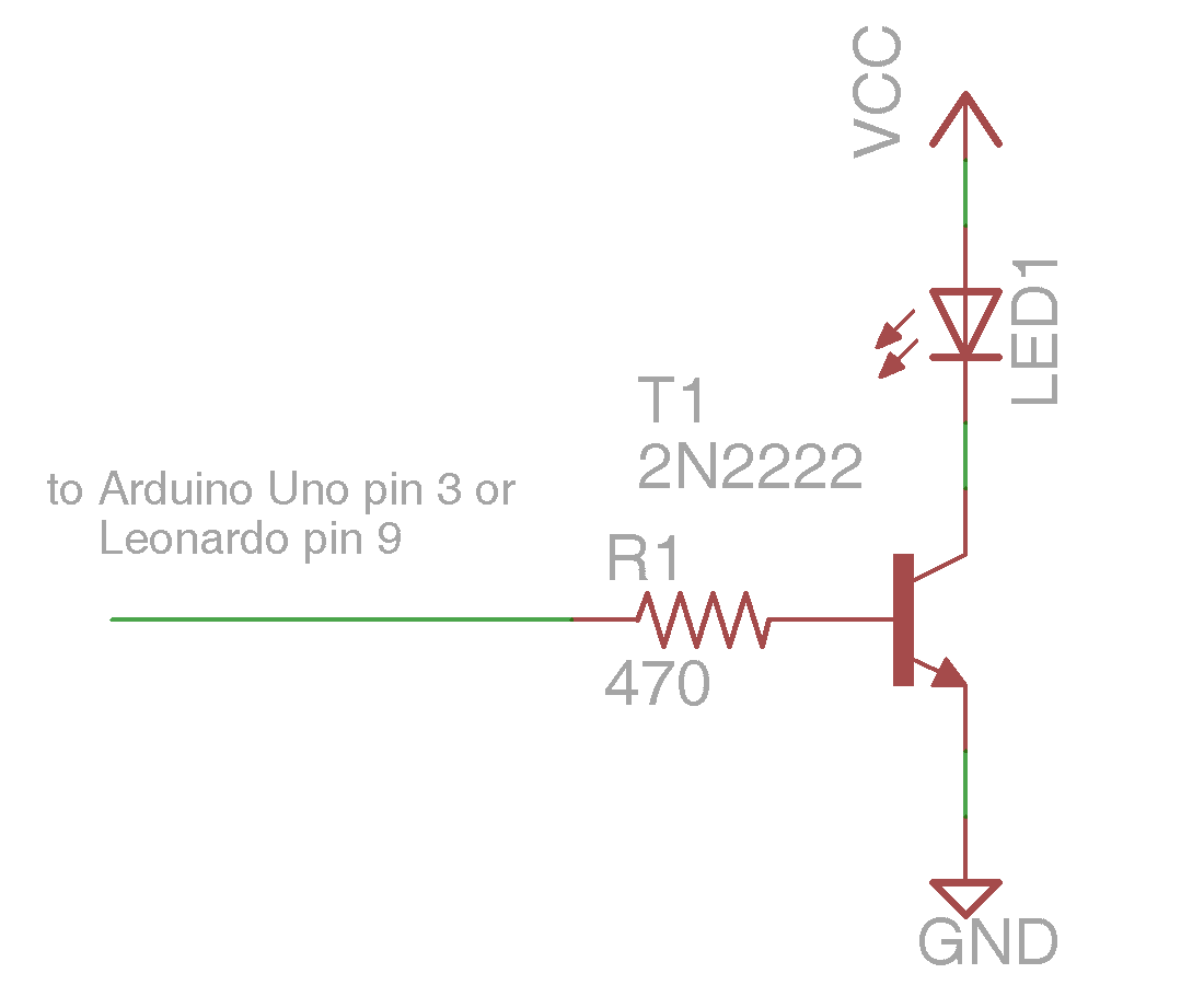
Here is another prototype version of my circuit using two LEDs. It’s based on information I learned from the people in the Adafruit forum. I call it my “IRIO Board” (Infra-Red Input/Output)
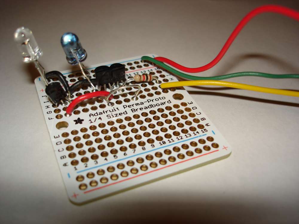
Prototype of My 2 LED IRIO Circuit
Part of the reason I wanted to redesign this little circuit was to try out a program called Eagle CAD from a company called CAD soft. It is available at http://www.cadsoftusa.com/ Is an expensive professional design program but there is a free version that will let you design small boards and certainly this one was small enough.
It gives you an extensive library of parts that you can use and there are ways to design parts of your own if you’re using a part that isn’t in the library. You basically do the design work on two different screens. On one of them you layout the schematic by dropping the pieces onto the screen, dragging them around with your mouse, and then connecting them together with wires. You then switch over to the circuit board portion of the program and arrange the components in the way you want them. On the circuit board side of the program, the components are already connected together with little rubber band like wires that stretch as you move the pieces around. There is a function called “rats nest” which helps you untangle the wires. Then you actually draw the traces to connect various parts together replacing the temporary rubber band wires with actual traces. In the free version you can only do a two player board top and bottom. The professional version allows you to do multiple layers. Two layers was going to be more than enough for me.
Here is the schematic that I designed. It has an NPN transistor driving up to 4 PNP transistors. Each of them in turn drives an IR LED. There is a 1k ohm that connects the NPN transistor to your Arduino board pin 3. There is also a place to put the IR receiver. In the schematic shown there are actually two IR receivers because I wanted to be able to mount the device pointing in different directions.
My IRIO Schematic from Eagle CAD
Here is a capture of what the circuit board screen looks like after I have arrange the pieces and put them in place. The red traces are on the top of the board. The blue traces are on the bottom layer. For those of you who are not familiar with it, the logo in the lower right corner is the “Open Source Hardware” logo. The four holes at the bottom are place to connect power, ground, input and output wires. There are a variety of ways you can put the IR receiver in the upper right corner.
My IRIO Board Layout in Eagle CAD
The white dotted lines show where you could cut off the left side of the board if you only wanted to use 2 LEDs instead of all four.
Now what to do with it? There are a variety of services which will take your Eagle CAD files and actually create the circuit board for you. If you tried to deal with a board manufacturer directly it would be very expensive. But there are services which take designs from a variety of hobbyists like myself, put all the little boards together on one big board, and ship it off to a manufacturer to be produced. They then take the big board, cut it apart, and ship it out to the hobbyists. I decided to use one such service called BatchPCB.com. You pay for the boards by the square inch plus a setup fee and shipping. My boards were under $5 each. I ordered three of them in with the other fees it was about $27. I placed the order on March 2 and it arrived yesterday on March 26. Here are front and back images of my professionally produced PCB board then I designed myself.
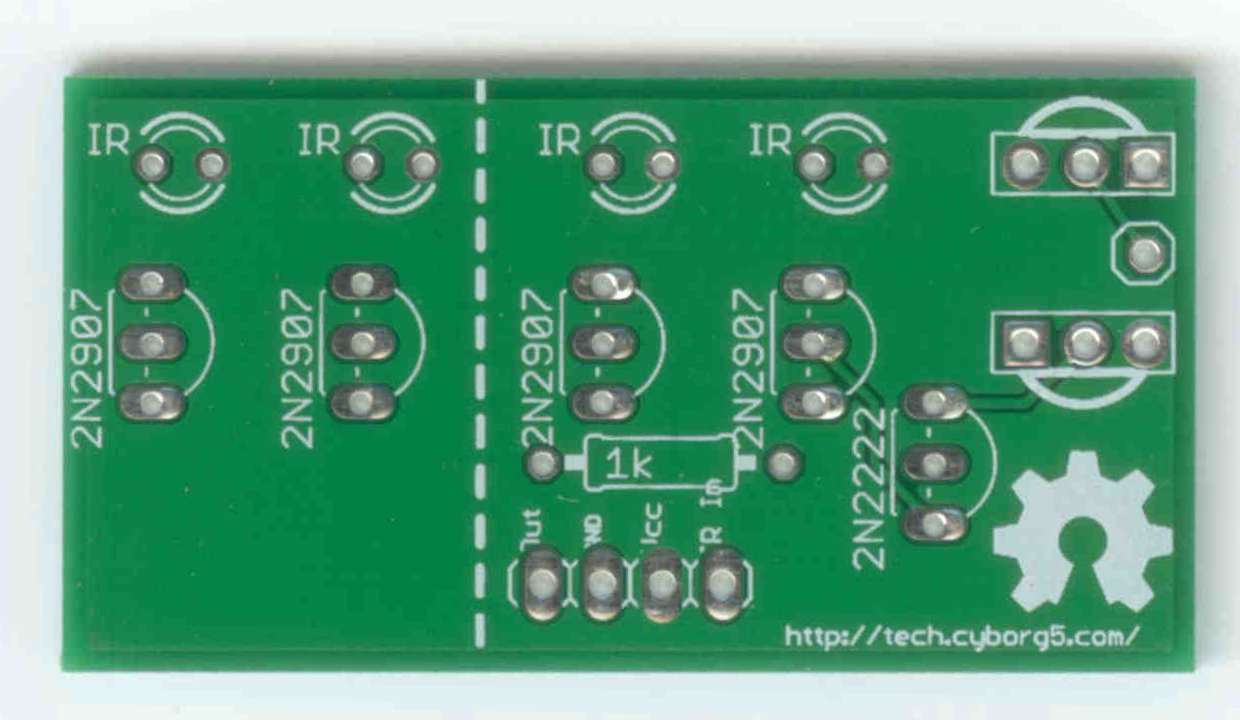
My IRIO Board (front)
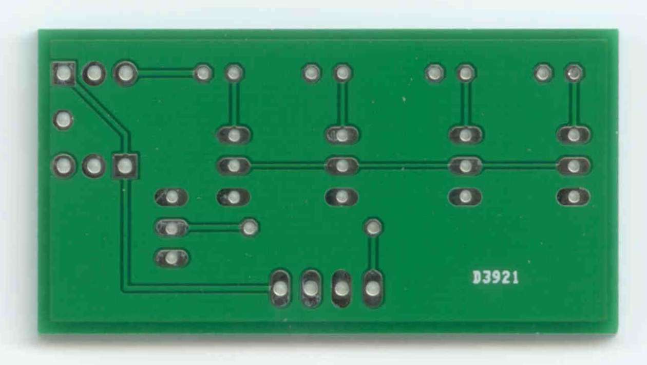
MyMy IRIO Board (back)
And finally… Here is what it looks like assembled. I tried it out and it works perfectly.
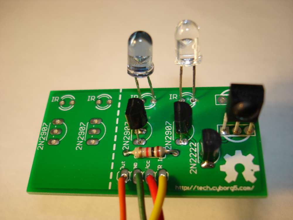
Assembled IRIO Board
This circuit however takes advantage of the fact that we are only sending brief pulses intermittently. We’re actually pushing more current through the devices then they are designed to take. One of the things I hope to do with this is to control an IR remote controlled toy helicopter. When pretty sure I will need to transmit signals continuously. So I designed another version of the board was some 33 ohm resistors to cut down on the current. Also when powering the Arduino from a PC USB port it draws too much current. It works okay on battery power or a USB charger but not directly on a PC.
I’ve submitted my new design to BatchPCB.com and hope to have it back in a couple of weeks. Here is a link to my updated board. It has not been tested on a real board but I did prototype it and it seems to work fine. I will post more information here when it comes. I also intend to write a tutorial on how to use this board with my IRLib Library for Arduino which you can read about here.