 When I first got my Printrbot Metal Plus 3D printer I had lots of difficulty getting the prints to stick to the build plate. I didn’t want to use blue painter’s tape because I already had Kapton tape on the plate and I wasn’t sure if perhaps I would someday be needing to print ABS which requires the heated bed. I didn’t think that would work very well with painter’s tape.
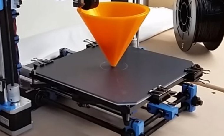
As it turned out I’ve never used ABS. I’ve only been printing with PLA and occasionally T-Glaze. I’ve been getting pretty good adhesion by using Elmer’s glue stick on top of the Kapton tape and heating the bed to 70°C. But before I came up with that solution I invested in a “zebra plate” from PrintInZ. This is a plastic print bed insertion that offers great adhesion with no tape and no heat for PLA. It is supposed to be good for ABS as well with heat. I purchased one of their plates at approximately 10 x 10″ which is the size of my bed. Unfortunately I didn’t realize that the way that the Printrbot bed is mounted there’s no way to use those large springy document clips to hold the plate in place as seen in this screen grab from a PrintInZ YouTube video.
The rails on which the print bed slides are located all the way to the very edge on each side of the print bed. There is an aluminum plate at the front and back of the print bed but even if you can get a clip over the edge of it, it would not clear the frame of the printer when the bed was all the way forwards are all the way backwards. There simply was no good way to get the plate to stick.
The company has a new product called a PrintInZ Skin which has an adhesive back on it. But one of the nice features of the plate is that if a part sticks too well, you can remove the plate and give it a slight warp and the part will pop off. Also the plate has a core consisting of a thin sheet of copper that will trigger the capacitance proximity sensor on the bed leveling system. The skin does not have a copper core and is probably too thick for the proximity sensor to be triggered on the metal bed beneath it. They do not recommend using it for that type of bed leveling.
Although I was getting reasonably good results with Elmer’s glue stick, it was a pain to have to reapply it and to clean it up after every print. I kept seeing more and more great reviews for the PrintInZ Plate so I finally had to come up with some system to easily mount and easily remove the plate.
We inspected the underneath side of the black aluminum plates at the front and back of the build plate. We determined that if we avoided the slide rails on each side and avoided the belt on the left side that we would be able to safely drill into the aluminum and bolt in some brackets that would hold the plate in place.
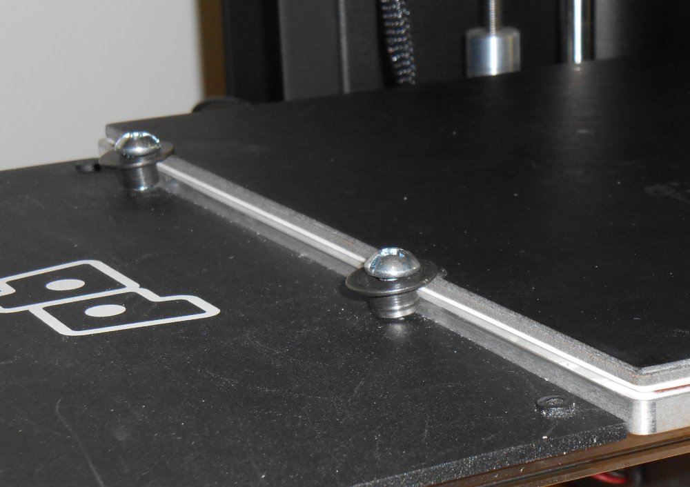
This photo shows the rear of the build plate where we put in some 1/4 – 20 screws with a spacer on top and a washer. You need to drill a hole slightly smaller than the 1/4 inch diameter and then use 1/4 inch thread tap to cut threads into the aluminum. That way you do not need a nut on the other end. You can screw directly into the aluminum plate.
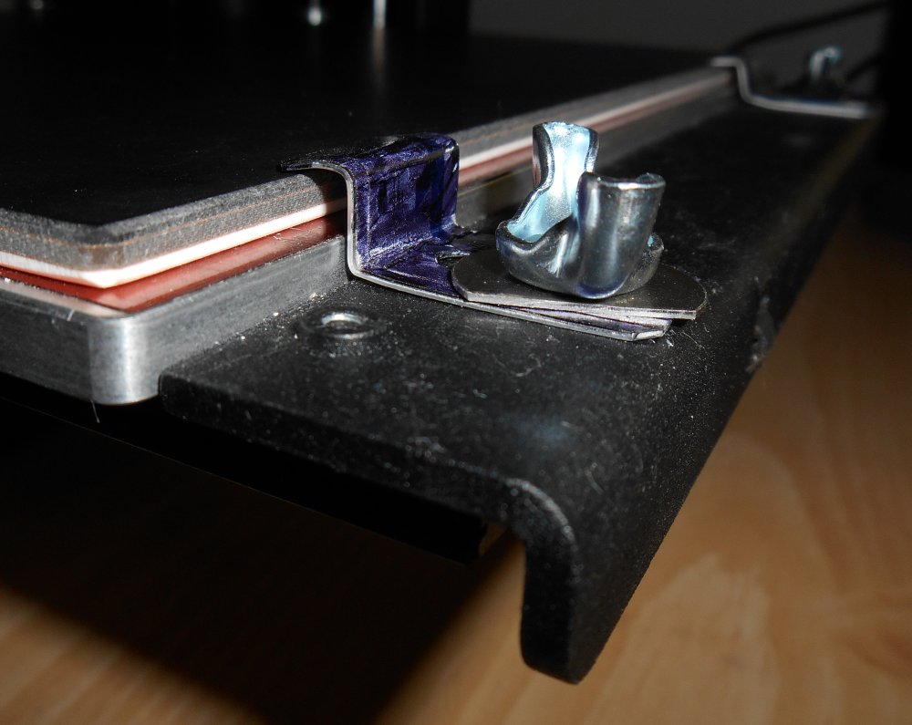
The screw on the left side of the machine (shown on the right here from the back) is halfway between the mounting rail and the belt. The screw on the other side is just inside the rail but we probably should have moved it a little farther towards the center. There is a microswitch inside the machine that limits the Y-axis travel and if the screw is too long it will hit that switch. You also of course need to make sure that the screws do not go so deep that they catch on the lip of the frame of the machine. As long as the power is turned off, you can manually slide the build plate forwards and backwards to ensure that the screws do not catch on the edge of the frame.
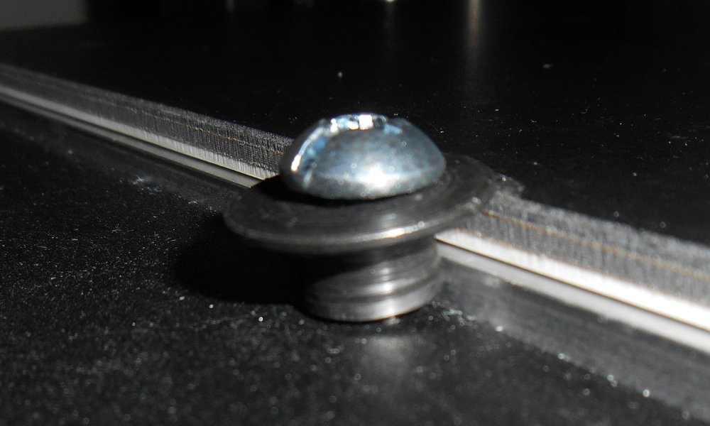 We accidentally drilled the rear holes too close to the build plate so that the spacer would not fit. We had to grind a flat side on the spacer to get it to go in. If you drill your holes out a tiny bit from the build plate and use a slightly larger washer you can avoid that problem.
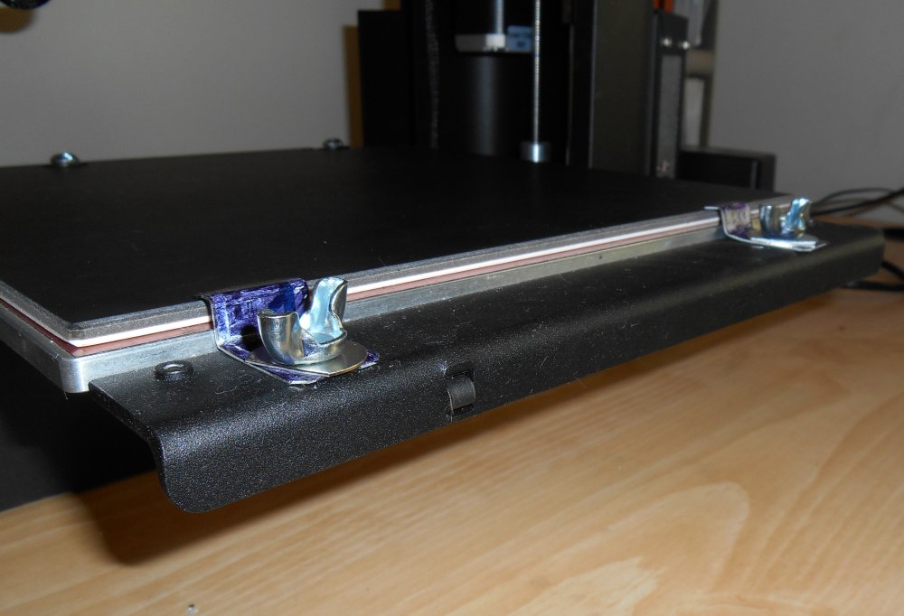
On the front we could’ve done the same thing but we wanted to make it easy to remove the plate in case we needed to warp it to remove a piece. Instead we took some scrap sheet metal (actually we cut up an old license plate) and fashioned some brackets. We drilled the holes very close to the front edge of the black aluminum plate that is at the front of the build plate. The brackets have slotted holes. We used 1/4″ – 20 wing screws to hold the brackets down. The brackets have a slot in them so that you could loosen the wing screws about one turn and slide the brackets forwards away from the build plate. Again on the left side we are halfway between the left rail and the drive belt.
One problem is that when the printer does the automatic bed leveling procedure, it touches down in three far corners of the build plate. It starts with the back left and then goes to the front left and finally the front right. We had hoped that the brackets were small enough that it would clear everything when it did the Z probe sampling. Unfortunately on the left side, the probe barely touched the left bracket. If we had drilled that hole just a couple of millimeters to the right or had put it to the right of the belt completely then it would’ve hopped over the bracket as it traveled from the left front corner to the right front corner. On the right side, the nozzle and the Z probe cleared the bracket but a tiny corner of the fan shroud touched the bracket. Again had we move the entire thing a fraction of an inch to the left it would’ve cleared.
There is a possibility that depending on the height of the screws and washers in the back, that the fan shroud might also clip them. You need to ensure that anything you print doesn’t come close to the far corners of the build plate. It reduces the size of your printable area but it is rare that you would have to build something that reaches all the way to the four corners of the plate.
Rather than re-drill and re-tap the holes we decide to fix it with software. We decided to only limit the front edge because the automated bed leveling required it. We did not artificially adjust the software to clear the back edge. We will just be careful never to print anything back that far. There are two places that you need to adjust the software. You need to adjust the firmware in the Printrbot itself. And then you also need to adjust the printing software you are using to tell it that your build plate is slightly smaller than expected. We use both Cura 15.04 and Simplify 3D software to drive the printer. We will describe what needs to be changed.
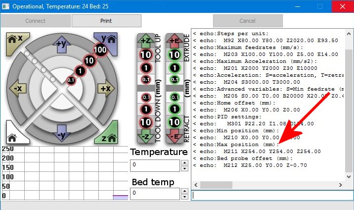
First to adjust the firmware we loaded Cura and called up the control panel. There are G-code commands that you need to type into the control panel. First type the command “M501” which will give you a printout of the current settings. You might want to drag your mouse across them and do a cut-and-paste and save the values just in case you accidentally mess something up. Here are the values that I had.
Note you can click on any of these images for larger versions.
> M501
< echo:Stored settings retrieved
< echo:Steps per unit:
< echo:  M92 X80.00 Y80.00 Z2020.00 E93.50
< echo:Maximum feedrates (mm/s):
< echo:  M203 X100.00 Y100.00 Z5.00 E14.00
< echo:Maximum Acceleration (mm/s2):
< echo:  M201 X2000 Y2000 Z30 E10000
< echo:Acceleration: S=acceleration, T=retract acceleration
< echo:  M204 S3000.00 T3000.00
< echo:Advanced variables: S=Min feedrate (mm/s), T=Min travel feedrate (mm/s), B=minimum segment time (ms), X=maximum XY jerk (mm/s),  Z=maximum Z jerk (mm/s),  E=maximum E jerk (mm/s)
< echo:  M205 S0.00 T0.00 B20000 X20.00 Z0.40 E5.00
< echo:Home offset (mm):
< echo:  M206 X0.00 Y0.00 Z0.00
< echo:PID settings:
< echo:   M301 P22.20 I1.08 D114.00
< echo:Min position (mm):
< echo:  M210 X0.00 Y0.00 Z0.00
< echo:Max position (mm):
< echo:  M211 X254.00 Y254.00 Z254.00
< echo:Bed probe offset (mm):
< echo:  M212 X25.00 Y0.00 Z-0.70
We are only interested in the last two items. The value “M211” is the maximum position and we will want to reduce the Y value to 244 instead of 254. Type in the commands…
M211 Y244
M500
M501
The first command changes the value. The “M500” saves the value. And then the “M501” displays the results again to verify it.
The other thing we need to change is the bed probe offset value M212. As you can see I had my Z value set at -0.70. This value sets how high off the print bed your first layer is set. I wasn’t sure how the Z probe would measure the copper plate embedded in the PrintInZ compared to the plain print bed with a Kapton tape over it. So I sent the value higher to about -0.30 and printed the small 3 mm test piece. I then lowered the value a couple of tenths at a time until the print looks good. As it turns out my original value of -0.70 was okay but there was no guarantee that it would’ve been. I suggest you do the recalibration. As before you would type
M212 Z-0.30
M500
M501
The other commands save and re-display the values.
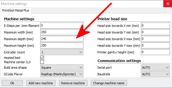
Now you need to tell Cura that your print bed is smaller. On the menu at the top click on “Machine-> Machine settings…”. Change the Maximum Depth from 250 down to 240. I would’ve expected these values to be 254 rather than 250 but these are the recommended settings from Printrbot.
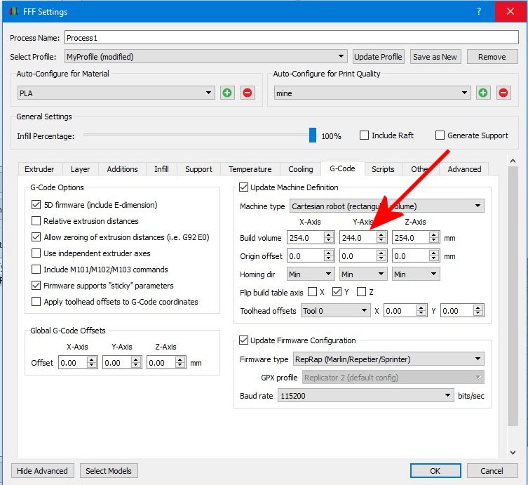
I also use Simplify 3D for printing. To adjust the settings click on the “Edit Process Settings” and under the tab labeled “G-Code” change the “Build Volume” in the Y-Axis from 254 down to 244. The default 254 makes more sense to me than the 250 in Cura. On the other hand one time I tried to print an object extremely close to the maximum X-Axis value and when it was drawing the rim before the print it reached the limits and the machine made a grinding noise. So you might want to think about changing all of these values to 250, 240, 250. After change in the value, click okay.
I’ve been able to successfully print using either printing software and I’m extremely satisfied with the PrintInZ Plate build plate. It really works very well as advertised. I highly recommend it.
Here is my appearance on the Adafruit Google+ Show and Tell on Wednesday, January 4, 2017 to describe this project.