Here is yet another video from Adafruit Show-and-Tell showing off the revised version of my IRIO circuit board for transmitting and receiving IR signals.

Adafruit Show-and-Tell sticker I earned for this presentation.
Here is yet another video from Adafruit Show-and-Tell showing off the revised version of my IRIO circuit board for transmitting and receiving IR signals.
Adafruit Show-and-Tell sticker I earned for this presentation.
This is the first in series of articles on using my infrared remote library for Arduino. In this installment we’re going to show you how to set up the hardware and how to run a quick demo sketch. You can find out more about the library on my IRLib page.
In order to detect a single from IR remote control such as you might use for your TV or home entertainment system you need an IR receiver module. Typically I use a unit I get from Radio Shack. You can also buy a similar module from my favorite supplier Adafruit.com. See the links at the end of this post for places where you can buy all of the parts mentioned in this article.
Pin 1 (on the left as you looking at the lens) needs to be connected to a input pin of the Arduino. It can be any could be any pin that doesn’t conflict with anything else you’re doing with the device. All of the examples in the library assume you are connected to pin 11 so we suggest you use it. The center pin 2 connects to ground any right-hand pin 3 should connect to your +5V power supply. If you are using a different microcontroller that runs at +3V this device will work at that voltage.
The simplest output device is simply an infrared LED and a current limiting resistor. IR LEDs can be purchased from a variety of places. Again see the links at the bottom of this post for sources. You are limited to using PWM pins for output because we use the PWM feature to modulate the signal. The default pin to use on Arduino Uno or other ATmega328-based controllers is pin 3. This particular pin is connected to “timer 2” of the chip. However the Arduino Leonardo and other controllers based on the ATmega32u4 does not have a “timer 2”. On these devices the default is to use timer 1 and pin 9 for output. We will talk more later about other options for timers and how to use this library on other types of hardware. For now all you need to know is if you have an Uno you should use pin 3 or a Leonardo use pin 11. Connect a 100 ohm resistor in series with the LED. Make sure you get the polarity of the LED correct. The shorter of the two leads should connect to ground. The longer lead connects to the resistor which in turn connects to the Arduino. Here is a schematic for the simplest setup. Note this post was edited on 2/5/2014 to correct the polarity. After telling you to be sure to get it right, I had described it wrong. The schematic has always been correct but my description was wrong. Sorry about that.
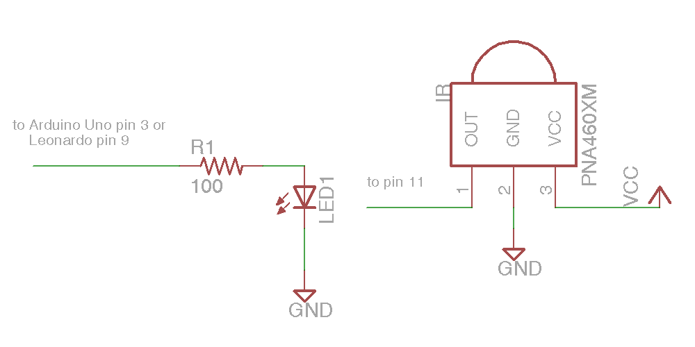
Simple IR I/O Schematic
That was the absolute simplest schematic however the output from the IR LED will be pretty weak because the output pins of Arduino cannot supply much current. You might want to consider adding an NPN transistor to drive the LED.
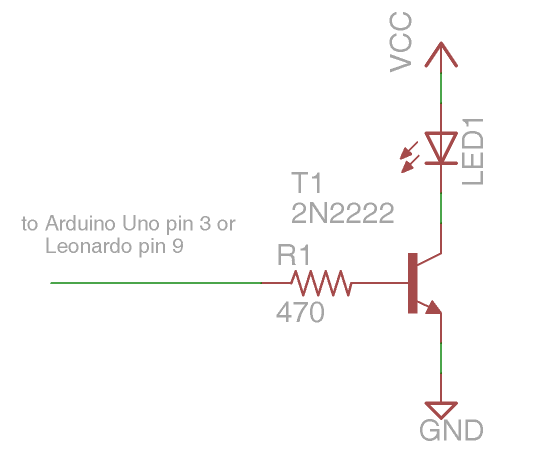
NPN Transistor Driving IR LED
Here is a simple sketch you can use to test if you are receiving IR signals. Is a stripped down version of the example sketch “IRrecvDump” that is in the examples subdirectory of the library.
/* Receiving IR signal and dump the details */

#include

//create a receiver object

IRrecv My_Receiver(11);//Use input pin 11
//create a decoder object
IRdecode My_Decoder;
void setup()
{
Serial.begin(9600);//We will read the output on the serial monitor
My_Receiver.enableIRIn(); // Start the receiver
}
void loop() {
//Loop until we get a signal and pass it to the decoder
if (My_Receiver.GetResults(&My_Decoder)) {
My_Decoder.decode();//decode the signal
My_Decoder.DumpResults();//dump the results on the serial monitor
My_Receiver.resume(); //restart the receiver
}
}
Upload the sketch and start the serial monitor on the Arduino IDE. Point a remote control such as a TV remote at the receiver and press a button. It will dump the information about the signal received. If it’s a protocol with the library understands it will tell you which protocol and it will give you a hex number of up to 32 bits that is the code for that particular function.
To test your transmitter, first determine the 32 bit hex code and protocol that the library can decode. A good example would be the power off/on button of your device assuming that your protocol is supported. As an example I sent a power signal to my Sony DVD player. The dump program tells me that it is a 20 bit code that is Sony protocol and that the value is 0xa8bca. The following sketch is a version of the example “IRsendDemo” in the examples directory of the library.
/*Transmit a power code for Sony DVD*/

#include
IRsend My_Sender;
void setup()
{
Serial.begin(9600);
}
void loop() {
if (Serial.read() != -1) {
//send a code every time a character is
//received from the serial port
//Sony DVD power A8BCA
My_Sender.send(SONY,0xa8bca, 20);
}
}
You will need to substitute the protocol name, the hexadecimal code, and the number of bits for whatever device you are operating. After you upload the sketch type a character into the serial monitor and press enter. Every time you transmit a character from the serial monitor, it will transmit the code you have programmed into the “My_Sender.send(…)” Function call.
In the installments which follow we will explain more of the details of the library including a more advanced circuit for transmitting codes. However for now this should get you up and running.
As promised here are some links to the hardware mentioned in this post
In the next installment will show how to receive and decode IR signals and use them to do something useful such as control a servo.
In April 2012 I begin work on a project to create an infrared remote control using an Arduino Uno. I downloaded a library of code called IRremote which was published by Ken Shirriff in his blog post here.
http://www.righto.com/2009/08/multi-protocol-infrared-remote-library.html
His library is available on github.com at https://github.com/shirriff/Arduino-IRremote
It’s a remarkable piece of work that makes it incredibly easy to receive, decode, and transmit IR signals such as are used for TVs and other consumer electronics. It supported NEC, Sony, RC5 and RC6 protocols as well as a raw data mode and he later added a 32-bit hash code version. Note: so I don’t have to remember constantly have to spell “Shirriff” I’m going to refer to his original library as the KS library.
However I needed to add some additional protocols of my own. It took a lot of research from a variety of sites but I eventually found a pair of websites that will especially useful in helping me to understand the various protocols available.
One especially useful site is this one which I believe KS cites in his blog http://www.sbprojects.com/knowledge/ir/index.php
However the one that had the most information is this one http://www.hifi-remote.com/johnsfine/DecodeIR.html
It uses a notation called IRP notation that is insanely difficult to understand but once you do it is a very concise way of describing an IR protocol. I used that reference to determine that my Bright House cable boxes which are either Scientific-Atlanta or Cisco user protocol called “Panasonic old”. It also helped me identify NECx and Samsung36 protocols which I needed to implement for various devices I have.
After after adding several of these protocols to the original KS library I realize there was a lot of redundant code being created. Also the way it was written you either had to use all of the protocols at once or you had to create your own custom version in which you deleted or commented out the protocols you didn’t need. Although the code was written in C++ it really didn’t take advantage of object-oriented programming practices for which this application was especially suited. What we really needed was a variety of decoder objects based upon a base object that could be extended by additional protocols without having to modify or recompile the original library.
Also found it a bit difficult to understand what part of the code was hardware related dealing with timers and interrupts and PWM signals versus the encoding and decoding of protocols. Once you understand the protocols you really don’t need to know the hardware specifics. In many ways that’s the whole purpose of a library is to make things as “black box” as possible. The user doesn’t need to know the internal details, only the program interface.
For my own deeper understanding of the code and as a programming exercise I embarked upon a almost complete rewrite of the entire library using the principles of object-oriented programming. I am now ready to release my rewritten library on github for others to use. I did not created as a fork of the original KS library because the rewrite is so extensive that it really doesn’t work as a patch to the original code. I’ve also renamed it because it isn’t really very backward-compatible with the previous code at least from a software standpoint. If you have hardware configured for the previous library it should work out of the box with this library.
I also want to acknowledge the work of TKJ Electronics who have created a fork of the KS code. I use their version to obtain additional information about use of the library with other types of Arduino boards other than the standard Arduino Uno. This was especially helpful to me when I needed to point the code to the Arduino Leonardo especially since the Leonardo does not timer 2 and the pinouts are different. The timer and more detection information from this fork has been included in my rewritten library.
Because my library is such a major rewrite and is not backwards compatible I have given it a different name and have not created it as a fork of either of these two predecessor libraries. I have to acknowledge that this is my first publication of code using github and I really don’t know what the proper protocol is for creating a work based on someone else’s material. If I violated some custom or rule in the open source community please feel free to contact me and I will adjust the linkage of my github pages appropriately.
While much of the code is well documented and includes a variety of example sketches, my intent is to create a series of blog posts here which gives further explanation of how to use the library and explains in more detail some of the example sketches. I also hope to write a post explaining how to use the IRP notation. But for now I just want to get the code out there so that people can give me feedback and perhaps start using it themselves.
Here’s the link to my new library which I call “IRLib”
https://github.com/cyborg5/IRLib/
Here is a page where I link to all of my blog posts related to this library.
http://tech.cyborg5.com/irlib/
I welcome your feedback.
Adafruit Show-and-Tell sticker I earned for this presentation.
This week I took the opportunity to share my own creation which I call “A Remote Control Remote Control”. It’s a gadget I built so it’s easier for me to work a TV remote while I’m in bed. It’s based on the Arduino Uno microcontroller.
Typically during the live chat sessions participants hold up there gadgets and demonstrate them live on a WebCam but that wasn’t going to be practical for me so I decided to create a premade YouTube video to demonstrate my project. I then got on the WebCam live discuss it with the hosts.
Other projects included a educational prototyping board that a woman from Canada had created for her local school system. A guy who made a gag Christmas presents for a friend or relative. When you open the box and had blinking lights and the fish headed guy from Star Wars yelling “It’s a Trap!”. And what appeared to be about a 10 or 12-year-old kid who had an Arduino controller, the blinking LEDs, and a thermal text printer. I’m not really sure what it did but it was cool for a kid’s age. Another guy had a Arduino/Raspberry Pi controlled engraving machine that was pretty cool.
Here is the entire 30 minute online chat.
Here is the video that I showed at the beginning of the chat you want to see a better look at what I was doing then was available during the live presentation.
I will probably go back and share more of my projects including my IR remote control mouse and keyboard emulator. I’m also working on a remote that will replace the remote I use on my wheelchair. That will have to wait until after dad recovers from his pacemaker surgery. The chat is at 9:30 PM on Saturday nights and that won’t work with the guy I have coming in to put me to bed about that time.