Taking a Tour of My Assistive Technology

Last week I was visited by my friend Bill Binko who helped me build a new version of my ultimate remote. I will post a new blog post about that remote soon. While he was here we shot some video that gives an overview of various assistive technology that I use on a daily basis including a demonstration of the newest version of the remote. Here is the YouTube video.

Sometimes Perfect Wiring is Wrong

The image above is the interior of a specialized version of my Ultimate Remote. It does mouse and keyboard control for my laptop via USB plug-in. It also will do Bluetooth switch control on my iPad or iPhone. Like my other specialized remotes, there is an LCD screen and an Adafruit Feather M0 BLE. But what really makes this one special is that it includes a relay that can be connected by cable to a nurse call system at St. Vincent Hospital. The cable has a standard quarter-inch mono headphone plug on the other end that plugs into the wall in the hospital room. The white rectangular box on the right side of the image is a relay that can be triggered to call the nurse. By using a mechanical relay, it isolates my electronics completely from the hospital’s nurse call system. Although the hospital has allowed me to plug a cable with a simple pushbutton on the other end into their system, I don’t know if they will allow me to plug in this more advanced system. But I built it anyway just in case. The problem is, I can only handle one set of buttons at a time. Either use my Bluetooth and USB mouse and keyboard system or I can use the nurse call system. This box would allow me to do both at the same time.

The St. Vincent Hospital system is wired so that it is normally closed. When you push the call button, the circuit opens and it triggers an alarm to call the nurse. The system used to be normally open years ago. But someone realized that if you accidentally pull the cable out of the wall there’s no way to know that it is disconnected. With a normally closed system if the cable gets pulled out it would trigger the alarm. This system is not used for everyday patients. Most patients use a nurse call button that is wired into the bed. The jack in the wall is only used for specialized call buttons. But because their system is normally closed, you can’t just have an empty jack. Otherwise the alarm would constantly ring. They have a small “keeper” plug that sticks in the hole when the system is not in use.

Here’s the problem… I recently toured a skilled nursing facility on the south side of town in Greenwood. There’s a possibility that if my sister could no longer be my caregiver, I might have to go there to live at least on a temporary basis until I could find some sort of group home residential setting. I was thrilled to see that there nurse call system use the same quarter inch mono headphone jack to plug into the wall. It looked identical to the jack hole at St. Vincent with one exception.

There was no keeper plug stuck in the hole. That means that the Greenwood facility is wired “normally open”. When you push the button, it closes the circuit. My standalone cable with a simple pushbutton that I’ve been using at St. Vincent for years as well as my newfangled box are both wired as normally closed. So I built another cable with another simple switch and wired it normally open. Now I have one of each. One for St. Vincent and one for Greenwood Healthcare. But of course I didn’t want to build an entire new box for the advanced version to use in Greenwood should I need to go there.

Take a closer look at the terminals connected to the relay in my box. There are three screw terminals just below the relay into which we connected 2 brown wires that run to a jack on the left side of the box. Take a moment to appreciate what a wonderful job my dad did when wiring up this box. Those two brown wires have been perfectly trimmed to the proper length. One of them goes to the left terminal which if you look closely in this image is labeled “NC” standing for “normally closed” and the center terminal is the common terminal labeled “COM”. Unused on the right is a terminal labeled “NO” meaning “normally open”. All I have to do to convert the system is to move the wire from the “NC” terminal to the “NO” terminal. But as you can see… Dad’s perfect wiring job means that the wire is too short. We were both so proud of how clean the interior of this box turned out. Now I’m going to have to get someone to replace the wire with one that is about a half-inch longer.

Sometimes perfect wiring is wrong.

Workaround for Saving Fusion 360 Projects with Linked Components

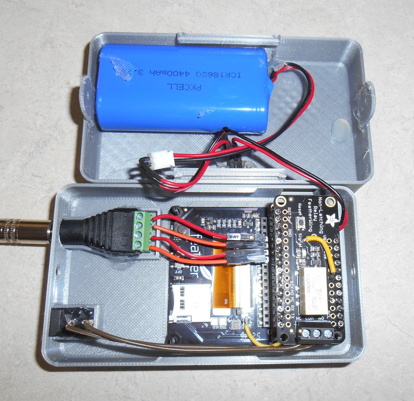
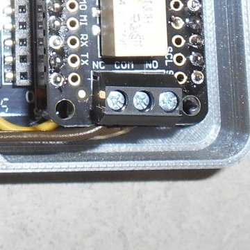
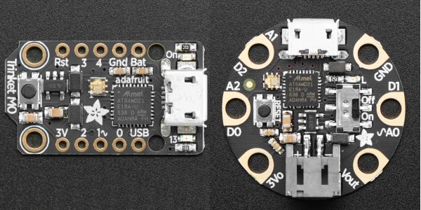
One of the nicest features of Fusion 360 is the ability to bring in components from other designs via a link into your current design. Then if the linked component gets updated, you can easily get the latest version for your project which imports that item. I’ve been building up a collection of designs of electronic parts that I use in my projects such as Adafruit Feather boards, sets of header pins, and other discrete components such as IR receivers and jacks and plugs. After laying out all of the components in Fusion 360, it is then much easier to build a 3D printing enclosure around those components. It also allows you to create really nice looking renderings of the project when writing tutorials.

Unfortunately when it comes time to share my open source designs with the world, it’s very difficult to save these Fusion 360 designs to my hard drive to later be uploaded to GitHub or Thingiverse. Fusion 360 stores its files in the cloud under your account most of the time. It does have the ability to save a design to your hard drive but not if that design contains linked components. If you try breaking the links it can create reference errors especially if the linked components themselves contain linked subcomponents.

There is a workaround however.

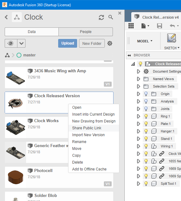
Open up your project and right click on the design and then click on “Share Public Link”.

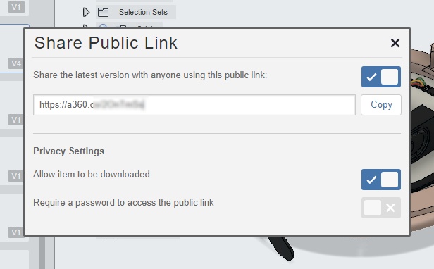
This will bring up a dialog box. You should check “Share the latest version with anyone using this link” and check on “Allow item to be downloaded”. Then copy the link and paste it in your browser.

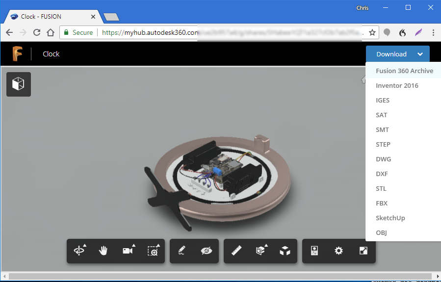
Your design will come up. In the upper right corner click on the “Download” drop-down and select “Fusion 360 Archive”. You will then be prompted to type in an email address and they will email you a link allowing you to actually download the file.

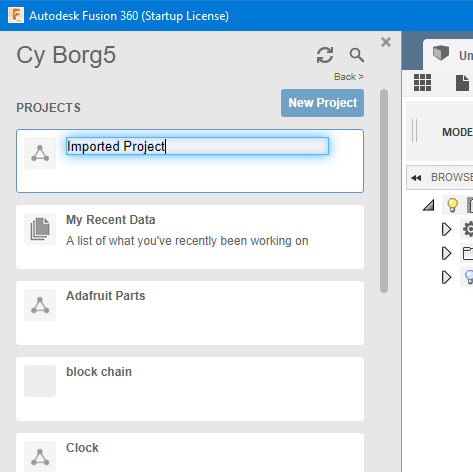
When your email arrives, you will have a link to the file that you can click on and actually download the file. The file format will be in “project.f3z”. Now that you’ve got the file, if someone else needs to open it, it doesn’t just open directly as you might hope. To import one of these files, you need to create a new project.

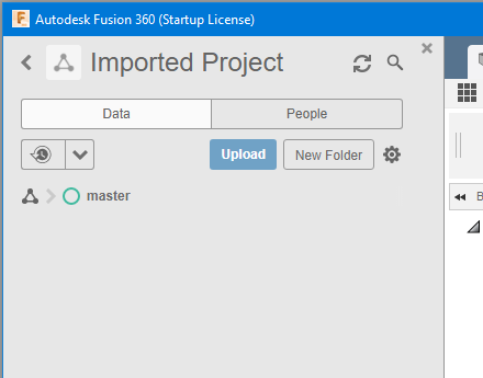
Open the project and at the top of the screen you will see an “Upload” button. It is called upload because all of Fusion 360 files are stored in the cloud under your account.

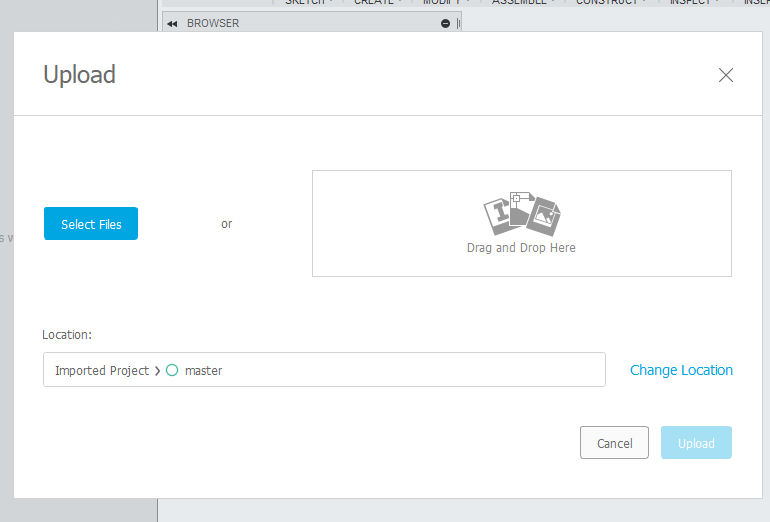
You will then get a pop-up dialog box that allows you to either drag-and-drop the file onto the dialog or browse your hard drive to select your file to upload. After a few minutes the file and all of its linked components will be uploaded and imported into the new project.

Nobody asked me, but it seems ridiculous that Autodesk makes you jump through all of these hoops. They ought to just allow you to do a “Save As” switch to word to your hard drive and have it create the f3z file directly. But at least this does solve the problem until Autodesk gets their act together.

IRLib2 Documentation Updated. Improved SAMD21 Support.

We are pleased to announce that IRLib2 support for SAMD21 has been rewritten and greatly improved. It will allow us to and support for more boards using that processor much more easily.

Also the documentation available in Microsoft Word, Adobe PDF, and EPUB e-book format as received a major update. This is the first update or rewrite since the extensive 116 page manual was originally written.

The updated code and documentation are now available on GetHub at https://github.com/cyborg5/IRLib2

The user’s manual now includes extensive details about support for SAMD21 processors such as those used in Arduino Zero, Arduino MKR series, Adafruit M0 boards including the Circuit Playground Express. We’ve also shared online a Google docs spreadsheet that gives a handy reference to pin numbers we support on the SAMD21 processor. You might find it a useful reference for other purposes as well. The document can be found at https://docs.google.com/spreadsheets/d/1rY79Hfl4f9e5TQBas_rWI3LeyTD8Hr-lhqi349ZwVXU/edit?usp=sharing

The documentation now also includes an explanation of protocol 12 CYKM which facilitates IR transmission of mouse and keyboard commands. These are especially useful in creating assistive technology devices for the disabled.

IRLib2 Updated to Support Trinket M0 and Gemma M0

We are pleased to announce the release of the latest version IRLib 2 which now includes partial support for the Adafruit Trinket M0 and Adafruit Gemma M0 boards. IRLib2 is a library for Arduino and related boards that facilitates the receiving, decoding, and transmitting of infrared signals such as those used by TV remotes. The code is available on Github at https://github.com/cyborg5/IRLib2

All forms of input are available on any of the digital input pins. There are limitations however on the output pins. Neither of the boards support hardware PWM on the pin 1. So that support will not be forthcoming. Theoretically the Trinket M0 should be able to use pin 3 or pin 4 but for some reason we cannot get that code to work. Similarly the Gemma M0 should be able to do output on pin 2 but it does not work either. Both boards are configured to default output on pin 0 and that works fine. Alternately you can use pin 2 on the Trinket M0.

Anyone who can help us figure out what’s going wrong we deeply appreciate it. Feel free to email me or discuss the issue publicly on Github issue #44 links here. https://github.com/cyborg5/IRLib2/issues/44

Late Update February 9, 2018: Resolved problems with Trinket M0. It can now use pins 3 and 4. Thanks to Limor “LadyAda” Fried who found the problem. I defy you to name another electronics CEO who will take the time to debug someone else’s library. Another in a long list of reasons Adafruit is such an amazing organization. It turns out there never was a problem with the Gemma M0. My initial tests must’ve been wrong.

IRLibCP Updated for Circuit Python 2.x

IRLibCP has been updated for use with Circuit Python 2.x and has been tested on Circuit Playground Express using Circuit Python 2.2.0. Note that previously this library was only available for use on Express style boards because they were the only ones that supported the required “pulseio” module. Theoretically with Circuit Python 2.0 and beyond that module is available on non-express boards but we have not yet tested the library on those platforms.

There have been no changes to the code since the previous version. This update merely provides updated .mpy files compatible with Circuit Python 2.x.

IRLibCP is available on Github at https://github.com/cyborg5/IRLibCP

How I Made 3D Printed Customized Christmas Holly Ornaments

My computer rendered Christmas card that I sent to friends and family this year had 3D printing as a theme. You can read all about it here.

My 2017 Christmas Card: Santa Adopts New Technology


Because many friends and family have never seen a 3D printer for the objects it creates, I decided to make a little Christmas to stuff in their Christmas cards. It’s a little piece of Christmas holly customized with their name on it. This video shows how I designed and 3D printing these little trinkets from my friends and family.

3D Printed Icosahedron Star Christmas Ornament

One of the fun things I like to do with my 3D printer is create Christmas ornaments. My radiused is this 20 pointed star shown here on my living room Christmas tree.

The basic shape begins with a 20 sided shape where each shape is an isosceles triangle. In order for it to print properly I had to cut that shape into two pieces. Then I separately printed the 20 spike shaped pieces to connect to each of the 20 triangles. One of the spikes includes a little loop so that you can hang the ornament.

We used super glue to put the pieces together. After gluing of the spikes onto the two halves of the central core it looks like this.

Then we finally glue the two sections together.

The files so you can print your own ornament are available on https://www.thingiverse.com/ by clicking here.

3D Printed Christmas Tree Illuminated by Circuit Playground Express

In 2015 I created some 3D printed Christmas ornaments as seen here. It occurred to me the other day that the tree ornament was just about the right size to sit on top of an Adafruit Circuit Playground Express. The Neopixels would reflect upward onto the ornament. I would have to resize it slightly and cut out some notches for the USB port and JST power connector.

I printed it using white PLA and I think it turned out pretty well. I also have some transparent T-Glaze filament that I may try as well. Here are some photos and a YouTube video showing how it looks.


I will post the code that I used to animate the lights sometime soon. It is currently written in Arduino C++ but I also want to create a Circuit Python version as well before I publish it.

Here is a link to the STL file on Thingiverse.

Here is a link to the original ornaments also on Thingiverse.

Switch Controled Assistive Technology Mouse Using Feather 32u4 and OLED Display

In the ATMakers.org Facebook page we’ve been discussing the development of an assistive technology device we are preliminarily calling APHID. It’s my belief that at least one version of our APHID device will need some sort of display. Here is a proof of concept of the device using a feather 32u4, OLED display and three switches. It does every kind of mouse control that you could imagine as well as the limited keyboard commands. This device is connected through USB but we could also make a Bluetooth version.