 In this lesson we will demonstrate how to receive IR codes and to use that information to do something useful. In this case we’re going to position a servo. You will need
- a 38 kHz IR receiver module
- a servo motor that uses PWM for positioning
- an IR remote control for a TV or VCR or any such device
At the end of this blog we will link to some sources for these items. If you do not have a servo available you should be able to follow the code given here to control relays or turn on and off LEDs or any other function you might control with an Arduino microcontroller.
Begin the process by wiring an IR receiver to pin number 11 on your Arduino as described in Lesson 1 of this tutorial. For this example you do not need to hook up an IR LED. We’re going to be receiving only. Also hook up a servo motor to power and ground and to pin number 9 on your Arduino. This diagram shows the complete set up.
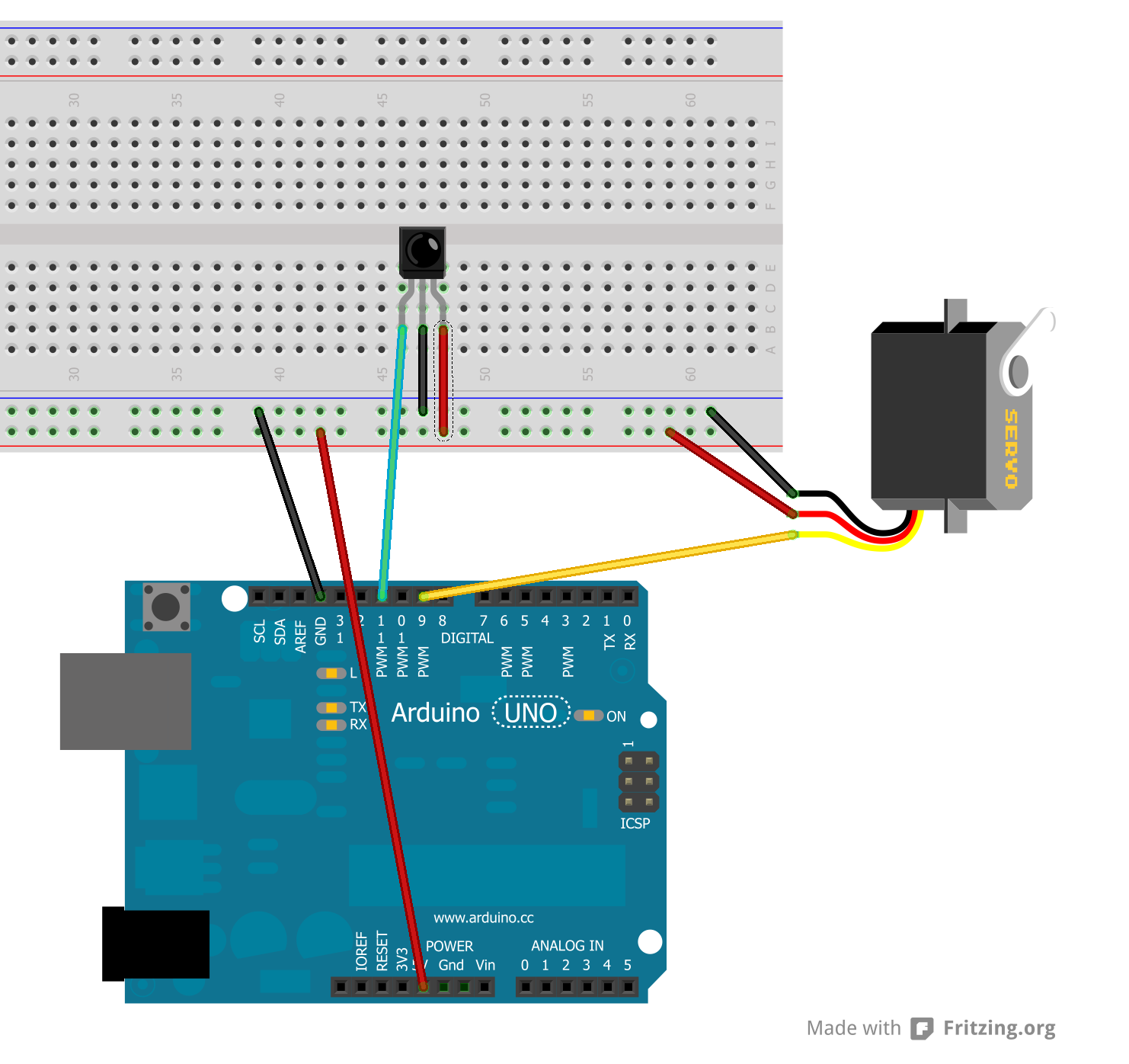
Hardware set up for IR servo control demo
Now you should load the IRrecvDump sketch from the examples folder of the IRLib library. We will use this sketch to determine what codes your infrared remote is transmitting. Run the sketch and open the serial monitor. Point your remote at the receiver and press the right arrow button. In this example I’m using a remote from my Sony DVD/VCR. The output on the serial monitor looks like this…
Decoded Sony: Value:86BCA (20 bits)
Raw samples(42): Gap:12550
  Head: m2300  s650
0:m1200 s600 1:m550 s650  2:m550 s650 3:m500 s650
4:m550 s650 5:m1150 s650  6:m1150 s600 7:m600 s600
8:m1150 s650 9:m550 s650  10:m1100 s650 11:m1200 s600
12:m1150 s650 13:m1150 s600  14:m550 s650 15:m550 s650
16:m1150 s650 17:m550 s600  18:m1200 s600 19:m550
Mark  min:500  max:1200
Space min:600  max:650
We really only need to concern ourselves with the first line of text of this dump. It says that the protocol that was decoded was “Sony” and that the value was 86BCA which is a number in hexadecimal code. The remainder of the information is unimportant to us. You need to write down the value received for each of the following buttons: right arrow, left arrow, up arrow, down arrow, select, and the number buttons 0 through 9.
We are going to presume that you are using a remote that has a protocol that this library understands. If the top line of the dump says “Decoded Unknown” then you either need to use a different remote or skip ahead to section on how to program your own protocol in a future lesson of this tutorial.
Now load the following sketch named “IR_Servo” and we will modify it with the codes you have obtained. You can click on the little orange pair of scissors to copy the code into your clipboard.
/* Example program for from IRLib – an Arduino library for infrared encoding and decoding
 * Version 1.0  April 2013 by Chris Young http://cyborg5.com
 * "IR_Servo" Control a servo using an IR remote
 */
#include <IRLib.h>
#include <Servo.h>
// You will have to set these values depending on the protocol
// and remote codes that you are using. These are from my Sony DVD/VCR
#define MY_PROTOCOL SONY
#define RIGHT_ARROW   0x86bca //Move several clockwise
#define LEFT_ARROW    0x46bca //Move servo counterclockwise
#define SELECT_BUTTON 0xd0bca //Center the servo
#define UP_ARROW      0x42bca //Increased number of degrees servo moves
#define DOWN_ARROW    0xc2bca //Decrease number of degrees servo moves
#define BUTTON_0 0x90bca  //Pushing buttons 0-9 moves to fix positions
#define BUTTON_1 0x00bca  // each 20 degrees greater
#define BUTTON_2 0x80bca
#define BUTTON_3 0x40bca
#define BUTTON_4 0xc0bca
#define BUTTON_5 0x20bca
#define BUTTON_6 0xa0bca
#define BUTTON_7 0x60bca
#define BUTTON_8 0xe0bca
#define BUTTON_9 0x10bca
IRrecv My_Receiver(11);//Receive on pin 11
IRdecode My_Decoder;
Servo My_Servo;  // create servo object to control a servo
int pos;         // variable to store the servo position
int Speed;       // Number of degrees to move each time a left/right button is pressed

void setup()
{
  My_Servo.attach(9);  // attaches the servo on pin 9 to the servo object
  pos = 90;            // start at midpoint 90 degrees
  Speed = 3;           //servo moves 3 degrees each time left/right is pushed
  My_Servo.write(pos); // Set initial position
  My_Receiver.enableIRIn(); // Start the receiver
}

void loop()
{
    if (My_Receiver.GetResults(&My_Decoder)) {
       My_Decoder.decode();
       if(My_Decoder.decode_type==MY_PROTOCOL) {
          switch(My_Decoder.value) {
            case LEFT_ARROW:    pos=min(180,pos+Speed); break;
            case RIGHT_ARROW:   pos=max(0,pos-Speed); break;
            case SELECT_BUTTON: pos=90; break;
            case UP_ARROW:      Speed=min(10, Speed+1); break;
            case DOWN_ARROW:    Speed=max(1, Speed-1); break;
            case BUTTON_0:      pos=0*20; break;
            case BUTTON_1:      pos=1*20; break;
            case BUTTON_2:      pos=2*20; break;
            case BUTTON_3:      pos=3*20; break;
            case BUTTON_4:      pos=4*20; break;
            case BUTTON_5:      pos=5*20; break;
            case BUTTON_6:      pos=6*20; break;
            case BUTTON_7:      pos=7*20; break;
            case BUTTON_8:      pos=8*20; break;
            case BUTTON_9:      pos=9*20; break;
          }
        My_Servo.write(pos); // tell servo to go to position in variable 'pos'
       }
     My_Receiver.resume();
    }
}
First you need to tell it what protocol you have received. Edit it into the line which reads
#define MY_PROTOCOL SONY
In general want to use the protocol name that was shown in the dump routine but it must be in all capital letters. If you want to get technical about it, legal values for this item are shown in the file “IRLib.h” at approximately line 53 which looks like this.
enum IRTYPES {UNKNOWN, NEC, SONY, RC5, RC6,
  PANASONIC_OLD, JVC, NECX, HASH_CODE,
  LAST_PROTOCOL=HASH_CODE};
Now back to the sketch… You need to edit into the sketch the values which you copied down for each of your buttons on your remote. Note that since these are hexadecimal numbers you should precede each one with “0x”. So in our example for the right arrow which produced a value of “86BCA” the line should look like this…
#define RIGHT_ARROW 0x86BCA
Note that in hexadecimal numbers when the letters “A” through “F” are used you may use either upper or lower case letters.
Once you have all of the values edited into the sketch, you should upload it. The servo will automatically center itself when the sketch has been uploaded and runs. Point your remote at the IR receiver and press the right or left arrow on your remote. The servo should rotate right or left as you push the buttons. If you push the select button on your remote it should center of the servo again. Pressing the numbers 0 through 9 will position the servo to fixed points 20 degrees apart.
By default, when using the left and right arrow buttons, the servo will rotate left or right by 3 degrees for each push of the button. By using the up arrow or down arrow buttons you can change how far the servo rotates. If you press and hold the down arrow for a couple of seconds it will change the default rotation to 1 degree. Pressing the up arrow button increases it to a maximum of 10 degrees. You won’t see anything happen when you push up or down but subsequent presses of left or right will be faster or slower. Here is a YouTube video demonstrating the project.
Now let’s look at the sketch line by line to see how it works. Just below the section which you edited we define several variables and objects
IRrecv My_Receiver(11);//Receive on pin 11
IRdecode My_Decoder;
Servo My_Servo;  // create servo object to control a servo
int pos;         // variable to store the servo position
int Speed;       // Number of degrees to move each time a left/right button is pressed
We create a receiver object and tell it to look for codes on pin 11. IR codes consist of a series of on and off signals called marks and spaces. The receiver object is an interrupt driven routine that looks for a signal every 50µs. It then stores in a buffer of integers the length of each mark or space in 50µs intervals. The buffer is located in the decoder object so we pass the address of the decoder to the receiver. There are technical reasons why we have separated these processes into receiver and decoder unlike other IR libraries. We will get into that in a future must. As mentioned we also have to create a decoder object. The decoder object looks at the values and attempts to determine which protocol was used and what the data values are that were encoded in the signal. We also create a servo object. Details on the servo library can be found here in the standard Arduino documentation. And we need integers to hold the position and the speed of the servo.
In the “Setup” function we initialize the servo on pin 9 set some default values and give it the command to move the servo into the default position. You then have to use this line
My_Receiver.enableIRIn(); // Start the receiver
To initialize the IR receiver. In the “Loop” routine we have a single if statement that is constantly looking for an IR code.
    if (My_Receiver.GetResults(&My_Decoder)) {
       My_Decoder.decode();
The “GetResults(address)” function returns true if a code has been received. It puts it into the decoder object whose address you passed to it. You then call the “decode()” method of your decoder.
We next check to see if the results received were from the proper protocol. No need to go through a bunch of testing if you picked up a signal from a different remote. We check to see if the “decode_type” is the right one using this if statement. The variable “My_Decoder.decode_type” is an enum which was shown earlier in this lesson and can be found in “IRLib.h”.
if(My_Decoder.decode_type==MY_PROTOCOL) {
Finally we check the “My_Decoder.value” in a switch statement to see if any of our defined codes are what was sent. If none of the case statements are activated, the code just falls through and updates the servo at its previous position.
It is important that we restart the IR receiver after any signal has been received even if it’s not one that we were interested in. This is done with the following statement
My_Receiver.resume();
You could easily modify the sketch to handle multiple servos doing all sorts of things such as positioning a robot arm or steering a remote-controlled car or doing any other function. You could hook up LEDs that would turn off on depending on which button to press on the remote. You could hook up relays to turn lights on motors off and on.
As promised here are some links to the hardware mentioned in this post
- Arduino Uno available at Adafruit.com or RadioShack.com
- Arduino Leonardo available at Adafruit.com
- 38kHz IR receiver module available at Adafruit.com or RadioShack.com
- Servos such as used in radio controlled models. Here are just a few examples
- Standard Micro Servo at Adafruit.com
- High Torque Micro Servo at Adafruit.com
- Standard Servo at Adafruit.com
- High Torque Standard Servo at Adafruit.com
- Not that you would need it but here is a nice little IR remote control from Adafruit.com which used the NEC protocol supported by this library.
In the next lesson we will focus on transmitting IR signals.
Thanks a lot for the library and tutorial, easy and effective, got mine working in a blink!!
Hello Chris..
First of all excellent effort to put together this blog.Clear example with very good explanation.
I would really appreciate your help for one of my problem related to controlling servo motor using Remote.
I am trying to control servo motor with remote control using Arduino Mega.
Problem I am facing is SERVO JITTER when using with IRLIb.I have upladed IRservo program and tested .It keeps on making noise .
I have tested oon 3 servos same issue.
Can you please advice any solution to eliminate this servo NOISE? I am continuously searching solution for this but unable to get the same.
Waiting for your reply
Thank you very much in Advance.
Regards
Shailesh
I’m sorry it took so long to get back to you about this. I’ve been tied up with other things. It’s most likely your problem is caused by too much current draw. When I originally designed this project it works okay on my desktop PC but when I went to demonstrate it on my laptop I got jittery results which sounds like what you’re getting. I tried plugging the Arduino into a battery pack instead and it works fine. My suggestion is get a good USB charger or a battery pack to run the device. See if that works.
Hi cy, great tutorial!
I have a timewarner cable in nyc box and remote. they use a scientific atlanta (UR5U-8700L-TWY), do you know if anyone has written protocol for that, or could you point me to a source to write my own. Wish I could use a different remote but I need to change channel on Time warner cable. When I press the “1” key I get the below data from IRrecvDump
Decoded Unknown: Value:0 (0 bits)
Raw samples(2): Gap:18422
Head: m300 s100
Mark min:32767 max:0
Space min:32767 max:0
Decoded Unknown: Value:0 (0 bits)
Raw samples(46): Gap:6250
Head: m250 s3050
0:m300 s3000 1:m450 s1200 2:m400 s2900 3:m250 s3050
4:m300 s1350 5:m250 s1350 6:m400 s1250 7:m350 s1250
8:m450 s2850 9:m300 s1350 10:m400 s1250 11:m400 s1200
12:m450 s2850 13:m450 s1200 14:m400 s1200 15:m450 s2900
16:m450 s2850 17:m400 s2900 18:m450 s2850 19:m400 s1250
20:m400 s2900 21:m400
Mark min:250 max:450
Space min:1200 max:3050
Decoded Unknown: Value:0 (0 bits)
Raw samples(2): Gap:37900
Head: m300 s3050
Mark min:32767 max:0
Space min:32767 max:0
This certainly is a strange one because it doesn’t have any kind of header in the front. Usually there is a long mark followed by a long space that serves as a header but this doesn’t have one. It looks as though a logic “0” is specified by something in the 350 range for a mark followed by a 1300 for a space. A logic “1” is specified by 350 mark followed by approximately 3000 space. In binary that comes out “11 0110 0001 0001 0011 1101” which is 0x36113b in hexadecimal. That gives us basically 22 bits of data and if you look closely the first 11 compared to the second 11 are the bitwise logical compliments on another. That is very similar to the PANASONIC_OLD protocol. In fact it is that protocol without the header. My Scientific Atlanta cable box uses PANASONIC _OLD. Try running the new “IRserial_remote” example in version 1.1 of my IRLib. Run the sketch, open the serial monitor, and type in “5,36113b” and see if it sends a channel 1 keypress to your box. My hope is that the box would ignore the header from the PANASONIC_OLD protocol and looked the next 22 bits and do the right thing. A Google search turned up the following article from a guy who is having the exact same problem with the exact same remote. Give me a couple of days when I’ve got some free time and I will try to write some code that would implement this strange protocol for you.
http://www.electro-tech-online.com/microcontrollers/123976-decoding-ir-control.html
thanks so much! if are able to write that protocol it would Rock!! In the mean time I’ll follow your suggestions and see if I can get it to work, thanks again :>)
Do you have a tutorial for IR remote control for DC motor at arduino too ?
I want to ask another question too. I want to use 2 servos now, how the coding will be change for 2 servos ? thanks.
To use an additional servo you just need to find another available PWM output pin. Also note that servos take quite a bit of current so you will want some sort of power supply that is more than just what a USB output on your PC can handle. And if you want to use DC motors in addition to servos you might want to get a motor shield such as http://www.adafruit.com/products/1438
HI
Thanks for the tutorial!
I have a problem though.
Whenever I want to upload the code onto my arduino I get the following message: IRrecv does not name a type, error message.
Please help.
Have you got my library downloaded and installed in the library folder?
Hi again.
Yes I do have your IR library installed and I have run some of the other examples on my arduino.
I have set the values for my remote.But keep getting the error message. Thanks!!
Here is my code, using arduino UNO:
#include
#include
// You will have to set these values depending on the protocol
// and remote codes that you are using. These are from my Sony DVD/VCR
#define MY_PROTOCOL NEC
#define RIGHT_ARROW 0xFF02FD //Move several clockwise
#define LEFT_ARROW 0xFFE21D //Move servo counterclockwise
#define SELECT_BUTTON 0xFFE01F //Center the servo
#define UP_ARROW 0xFF609F //Increased number of degrees servo moves
#define DOWN_ARROW 0xFF22DD //Decrease number of degrees servo moves
#define BUTTON_0 0xFFA857 //Pushing buttons 0-9 moves to fix positions
#define BUTTON_1 0xFF906F // each 20 degrees greater
#define BUTTON_2 0xFFB847
#define BUTTON_3 0x4FFF807
#define BUTTON_4 0xFFEA15
#define BUTTON_5 0xFFBO4F
#define BUTTON_6 0xFF9867
#define BUTTON_7 0xFFD827
#define BUTTON_8 0xFF8877
#define BUTTON_9 0xFFE817
IRrecv My_Receiver(11);
IRdecode My_Decoder;
Servo My_Servo; // create servo object to control a servo
int pos; // variable to store the servo position
int Speed; // Number of degrees to move each time a left/right button is pressed
void setup()
{
My_Servo.attach(9); // attaches the servo on pin 9 to the servo object
pos = 90; // start at midpoint 90 degrees
Speed = 3; //servo moves 3 degrees each time left/right is pushed
My_Servo.write(pos); // Set initial position
My_Receiver.enableIRIn(); // Start the receiver
}
void loop()
{
if (My_Receiver.GetResults(&My_Decoder)) {
My_Decoder.decode();
if(My_Decoder.decode_type==MY_PROTOCOL) {
switch(My_Decoder.value) {
case LEFT_ARROW: pos=min(180,pos+Speed); break;
case RIGHT_ARROW: pos=max(0,pos-Speed); break;
case SELECT_BUTTON: pos=90; break;
case UP_ARROW: Speed=min(10, Speed+1); break;
case DOWN_ARROW: Speed=max(1, Speed-1); break;
case BUTTON_0: pos=0*20; break;
case BUTTON_1: pos=1*20; break;
case BUTTON_2: pos=2*20; break;
case BUTTON_3: pos=3*20; break;
case BUTTON_4: pos=4*20; break;
case BUTTON_5: pos=5*20; break;
case BUTTON_6: pos=6*20; break;
case BUTTON_7: pos=7*20; break;
case BUTTON_8: pos=8*20; break;
case BUTTON_9: pos=9*20; break;
}
My_Servo.write(pos); // tell servo to go to position in variable ‘pos’
}
My_Receiver.resume();
}
}
Always read your earliest error messages first. That can screw up things later on down the list. In this case your definition of BUTTON_4 is bad. You have a letter “O” instead of a zero “0” in the third from last hex digit.
Thanks for the great IR library and tutorial for getting it up and running with servos.
One couldn’t ask for a better tutorial with working code.
It worked right away for me. The only thing that took a few seconds was fishing around for the library download. I didn’t realize it is in your main navigation till I clicked around the site for a few seconds.
I just ran it on my robot project at http://inventorartist.com/rolly-bot/.
My servos are different though since I hacked them into drives. So instead of getting position you get speed. Works like a charm.
Darcy
my code is ok and everything is ok . but when the motor is starting using remote it starts but from then my decode result shows unknown but it showed sony . i used motor driver but the same problem. yes sometimes its ok .
i use dc motor
I’m sorry I don’t have any experience using DC motors. The problem could be from electrical noise backing up to the power supply or perhaps the motor is drawing too much current and causing other things to fail. Anytime you are driving motors or servos you need have a good clean steady power flow. Also you need to make sure that the motor driver doesn’t interfere with interrupts or hardware timers. I’m not familiar with how motor drivers work so I don’t know if that would cause interference or not. Those are the only only suggestions I have.
Cy, thanks for all the time I know you put in refining the sketches. I wonder if you could expand the servo IR control to include the use of a pot in to vary the servo position, instead of simply using an IR remote transmitter. I have reworked another sketch and it works fine controlling the focus on my telescope using a stepper motor. I use the left/right for fine adjustments, the up/down for slightly coarser adjustments, and the A/C buttons for really coarse adjustments. I haven’t figured out how to interrupt the commands if I am moving the focus in the wrong direction yet, but I am still trying. But if I could ever get a servo with a multi-turn pot working it would be a better, more accurate method of focusing. Thanks for considering this request.
I’ve not work with stepper motors and only have limited experience with servos however from what I know about the subject, I think that they stepper motor would give you finer control. Servos aren’t very accurate in the positioning at least not compared to steppers. Also unless you use a continuous rotation servo you’re only going to get at most 180° of rotation.
Whenever I click verify for the IRrecvDump sketch…
I get the error:fatal error:IRlib.h:No such file or directory
compilation terminated.
please help to overcome this problem
That would indicate you don’t have the library installed properly. It cannot find the header file.
Hi,
I want to receive and decode the protocol of lego power functions infrared receiver.
The protocol specifications can be found here:
http://www.philohome.com/pf/LEGO_Power_Functions_RC_v120.pdf
Page 6 explains the protocol, page 11 shows how low and high bits are definded.
But I don’t know how to start here to add this new protocol. Can you help please?
I’m not had time to write chapter for the users manual on how to implement your own particles. But I took a brief look at the document that you linked and you should be up to do it by plugging the proper values into the generic send and receive methods. I really don’t know how much programming experience you have it take a look at the generic routines and parameters. See how they were used for protocols such as Panasonic Old.
Thanks for the Tutorial! How would I change the Code to add a second Servo? I’m trying to make one servo move on the up and down arrows and the second move on the left and right arrows. Your help is greatly appreciated!
Just attach the server to a different digital output pin and change the code to operate the other servo depending on what code is received. It’s a pretty simple change but you need to know how to program.
I am trying to do the same thing. If you figure out the code can you post it. Thanks.
There was a problem with this blog post because I changed the code formatting plug-in and formatted code was not displayed properly. Note however that this blog post refers to the original IRLib however IRLib2 has been updated and there is a version of the same project in the tutorial section of the user manual. Give the latest version of IRLib2 and read the manual into a tutorial section.