Recent updates to my IRLib2 Library for Receiving, Decoding, and Sending Infrared Signals have fixed long-standing problems with support for SAMD51 based boards. In addition to support for Adafruit Metro M4 we now also support Adafruit Grand Central M4 and Adafruit Feather M4 Express.
Last week I was visited by my friend Bill Binko who helped me build a new version of my ultimate remote. I will post a new blog post about that remote soon. While he was here we shot some video that gives an overview of various assistive technology that I use on a daily basis including a demonstration of the newest version of the remote. Here is the YouTube video.
We are pleased to announce that IRLib2 has now added support for the SAMD51 processor on the Adafruit Metro M4. Other M4 platforms will be supported as they become available.
The SAMD51 processor runs at 120 MHz. It has 512 KB flash and 192 KB RAM. This is a much more powerful processor than the M0 class SAMD21.
We support PWM output on pins 0-13 and input on any digital input pin.
We are pleased to announce that IRLib2 support for SAMD21 has been rewritten and greatly improved. It will allow us to and support for more boards using that processor much more easily.
Also the documentation available in Microsoft Word, Adobe PDF, and EPUB e-book format as received a major update. This is the first update or rewrite since the extensive 116 page manual was originally written.
The user’s manual now includes extensive details about support for SAMD21 processors such as those used in Arduino Zero, Arduino MKR series, Adafruit M0 boards including the Circuit Playground Express. We’ve also shared online a Google docs spreadsheet that gives a handy reference to pin numbers we support on the SAMD21 processor. You might find it a useful reference for other purposes as well. The document can be found at https://docs.google.com/spreadsheets/d/1rY79Hfl4f9e5TQBas_rWI3LeyTD8Hr-lhqi349ZwVXU/edit?usp=sharing
The documentation now also includes an explanation of protocol 12 CYKM which facilitates IR transmission of mouse and keyboard commands. These are especially useful in creating assistive technology devices for the disabled.
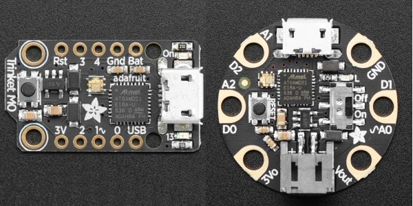
We are pleased to announce the release of the latest version IRLib 2 which now includes partial support for the Adafruit Trinket M0 and Adafruit Gemma M0 boards. IRLib2 is a library for Arduino and related boards that facilitates the receiving, decoding, and transmitting of infrared signals such as those used by TV remotes. The code is available on Github at https://github.com/cyborg5/IRLib2
All forms of input are available on any of the digital input pins. There are limitations however on the output pins. Neither of the boards support hardware PWM on the pin 1. So that support will not be forthcoming. Theoretically the Trinket M0 should be able to use pin 3 or pin 4 but for some reason we cannot get that code to work. Similarly the Gemma M0 should be able to do output on pin 2 but it does not work either. Both boards are configured to default output on pin 0 and that works fine. Alternately you can use pin 2 on the Trinket M0.
Anyone who can help us figure out what’s going wrong we deeply appreciate it. Feel free to email me or discuss the issue publicly on Github issue #44 links here. https://github.com/cyborg5/IRLib2/issues/44
Late Update February 9, 2018: Resolved problems with Trinket M0. It can now use pins 3 and 4. Thanks to Limor “LadyAda” Fried who found the problem. I defy you to name another electronics CEO who will take the time to debug someone else’s library. Another in a long list of reasons Adafruit is such an amazing organization. It turns out there never was a problem with the Gemma M0. My initial tests must’ve been wrong.
IRLibCP has been updated for use with Circuit Python 2.x and has been tested on Circuit Playground Express using Circuit Python 2.2.0. Note that previously this library was only available for use on Express style boards because they were the only ones that supported the required “pulseio” module. Theoretically with Circuit Python 2.0 and beyond that module is available on non-express boards but we have not yet tested the library on those platforms.
There have been no changes to the code since the previous version. This update merely provides updated .mpy files compatible with Circuit Python 2.x.
We are pleased to announce a very early pulmonary beta release of IRLibCP. This is a Circuit Python module for receiving, decoding, and transmitting infrared signals. It is a translation from the original IRLib2 written in C++
Because the module depends on the “pulseio” module of Circuit Python it can only be used on “Express” versions of Adafruit boards. Specifically Circuit Python Express, Feather M0 Express, and Metro M0 Express. It cannot be used on other versions of Circuit Python such as Feather M0 Basic or BLE nor on ESP 8266 platforms.
As previously mentioned this is a very early beta release. Further example programs and updated documentation will be coming soon as well as refinements to the modules themselves.
Also a bit of disclaimer… I began computer programming writing and BASIC when I was in high school in the early 1970s. I went to college and wrote Fortran and Pascal and God help me even a little COBOL as well as other programming language that don’t exist anymore such as Algol and PL/1. For the last 25 years I’ve written nothing but C and C++ with minor dabbling’s in JavaScript and PHP. But converting IRLib2 into Python is only the second Python program I’ve ever written. I’m sure experienced Python programmers will cringe when a see my code. Please be patient with me. I’m still learning. If you want to give me some constructive tips please send them to me at cy_borg5@cyborg5.com
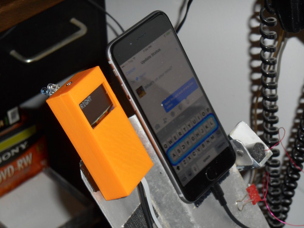
In late 2015 I built a piece of assistive technology that I called my Ultimate Remote. The device was an infrared remote for controlling my TV and cable box. It also had infrared mouse control for my computers. There were also limited keyboard commands mostly arrow keys, enter key, backspace and some control keys for doing cut-and-paste. Finally it was a Bluetooth device for doing accessibility switch control on my iPhone. I wrote about it in this blog post from January 2016.
The core of it was an Adafruit Micro BLE device which was discontinued shortly after I purchased it. Adafruit replaced it with the Adafruit Feather 32u4 BLE. The Micro BLE also had an ATMega32u4 which is one of my favorite 8-bit processors.
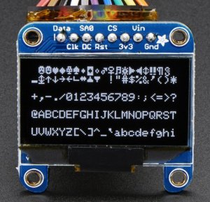
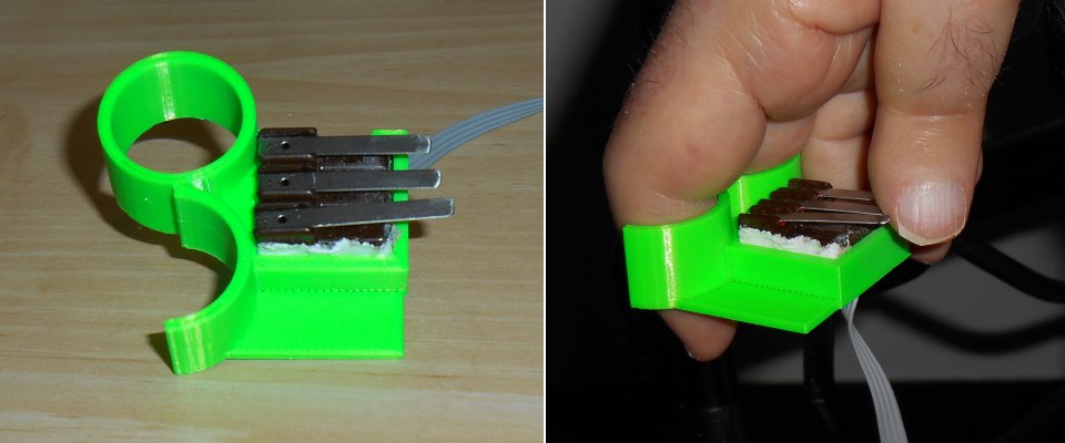
The display was a monochrome 1.3 inch 128×64 OLED graphic display. It also contained one of my infrared I/O boards although it only did output. I didn’t really need to read any IR codes. On the end of a long wire were three lever micro switches that I would hold in my right hand to control the device.
The device served me well for well over a year. It was critical to me during my recent hospital stay where I was on a ventilator and could not talk. I used the switch control to type notepad messages on my iPhone and communicate with the nurses and doctors. You can read about that adventure here.
The micro switches have always been the weakest link in my devices. I have to use switches that have a feather touch to them and that means they are very fragile. The switches get knocked around quite a bit and so it was inevitable that one of them would break. About a week ago one of the switches failed and we had to replace them.
I had planned for many months to rebuild the entire device. I had used up all of the program memory in the device and could not add any new features or any new IR commands. I did not have codes installed for my Blu-ray player and there wasn’t any room left. In fact one time I had tried to recompile the code and because one of the included libraries had been updated, the code wouldn’t fit anymore. I don’t know if it was the Bluetooth BLE library or the graphics display library but something changed. I had to go through my code and try to free up some space by eliminating some error messages or shortening other messages. I finally got it to recompile but the writing was on the wall that I needed to upgrade.
The obvious choice was to use a new Adafruit Feather M0 BLE. Instead of the traditional 8-bit 32u4 running at 16 MHz with 32K flash memory and 2.5K RAM, I would have a 32-bit ARM Cortex M0+ running at 48 MHz, with 256K flash memory and 32K of RAM. The main problem was that my infrared library IRLib did not support these newer 32-bit ARM processors.
I had just recently spent weeks researching the new processor and converting my infrared library to support the newer chips. The timing and frequency modulation portions of my IR code are extremely dependent on the internal timers of the processor and that is very hardware dependent. I had to learn a whole new system of timers and PWM frequency control to rewrite the code. Fortunately I got it running just in time.
Although I had the infrared code working on the new processor, and had a Feather M0 BLE available to build a new device, it should not have been necessary to rush the new device into construction. All we had to do was repair the old remote by replacing the micro switches. I already had another set of switches assembled in anticipation of building the new remote. All we had to do was cut the cable on the old one, splice in the new cable and everything would be fine.
Dad decided that rather than having a stiff, unsightly splice in the middle of my cable, he would open up the box, unsolder the old cable and solder on the new cable. He ended up completely disassembling everything to get at the wires that needed replacing. I appreciated that he would go to that trouble even though this device was going to get replaced probably in a month or two. Unfortunately this was a bad decision.
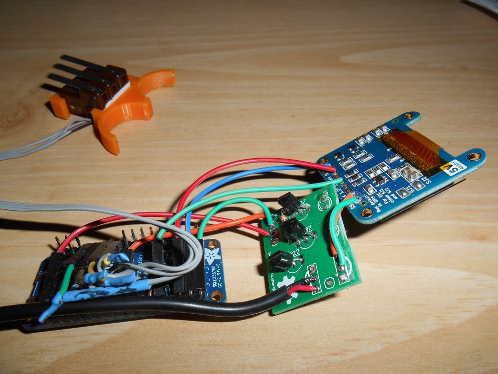
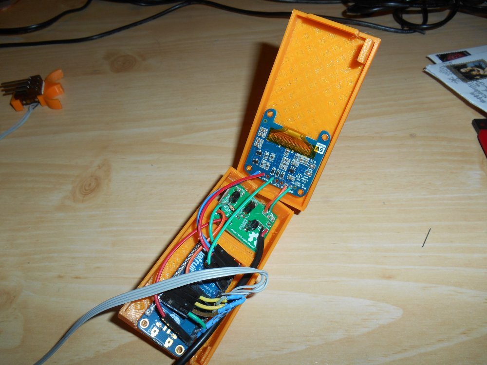
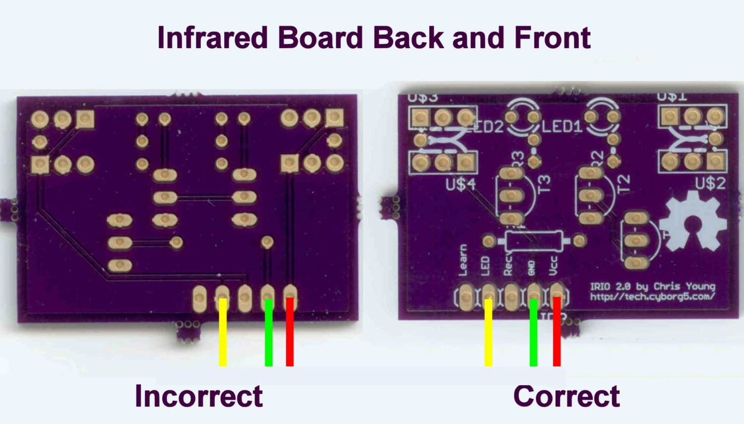
Above are photos of the interior of my original ultimate remote. As you can see the wiring is pretty complicated. Unfortunately I only have about four different colors of wires available so we had to use the same color wires for different purposes. For example there are multiple green wires used for different purposes. After replacing the cable to the micro switches, dad tried to plug everything back in the way it was. We plugged in the device and I tried pushing the buttons but nothing would happen. In the course of trying to figure out what was wrong he touched one of the infrared LEDs and discovered that it was very nearly becoming more red than infra. It was too hot to touch. Although we did not get a visit from the infamous “Blue Smoke Monster”, if we had left it connected very long we would’ve had at least smoke and possibly fire as well.
It didn’t take us long to find out that the culprit was 2 green wires that had been crossed. We fixed the wiring and plugged it back in. No heat this time. The device worked intermittently for about five minutes and then quit working altogether. It was obvious that we had burned out the IR LED at least and possibly the transistors driving them.
Fortunately I had sufficient parts to build a new IR output board so we spent the next afternoon building it and installing it. It would not work either! One of the problems we were facing was that we had assembled and disassembled the box many times. I had been using small gauge stranded wire with silicone insulation. That is very flexible and made it easy to route the wires in a tiny box. However several of these wires were soldered into through hole locations on the circuit boards. Right at the point where they are soldered in, they are extremely susceptible to breaking if they are bent back and forth too many times. A better solution would have been to put a header pin in the hole. Then we could solder the stranded wire onto the pin and cover it with a piece of heat shrink tubing. At this point it was too late to do that.
We tried repeatedly to diagnose the problem with the new IR board but every time we fixed one thing, something else would break. There was also the possibility that we had damaged the Adafruit Micro BLE board itself. As I mentioned earlier, that board has been discontinued so there was no possibility of replacing it. After two full afternoons of working on it, I decided to throw in the towel and put all of our efforts into building the completely new device that had been planning for months.
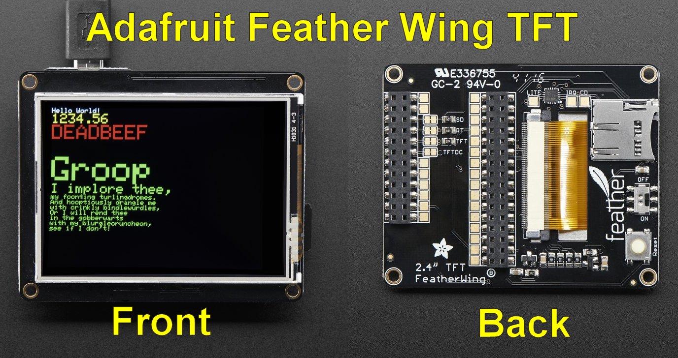
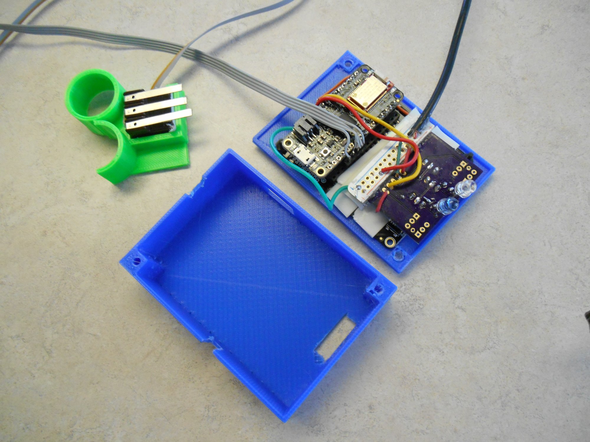
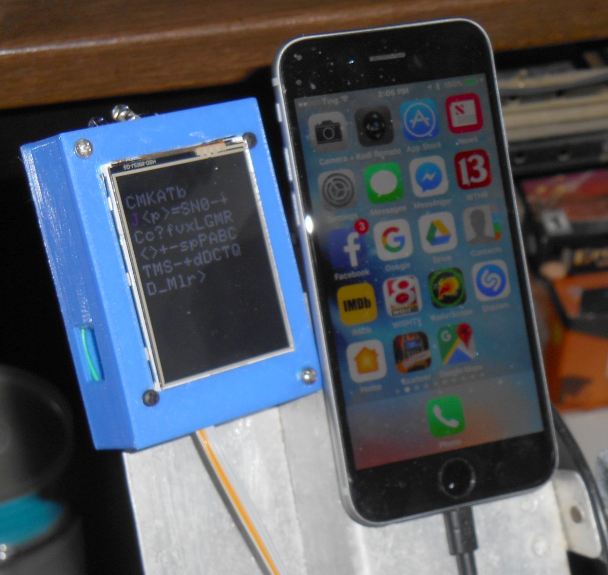
I had all of the necessary parts. The new device would have a much larger 2.4 inch TFT color graphics display instead of the 1.3 inch monochrome OLED. This device also features a resistive touchscreen however I don’t have any use for that feature. It also includes a slot for an SD memory card. I may come up with a future use for that.
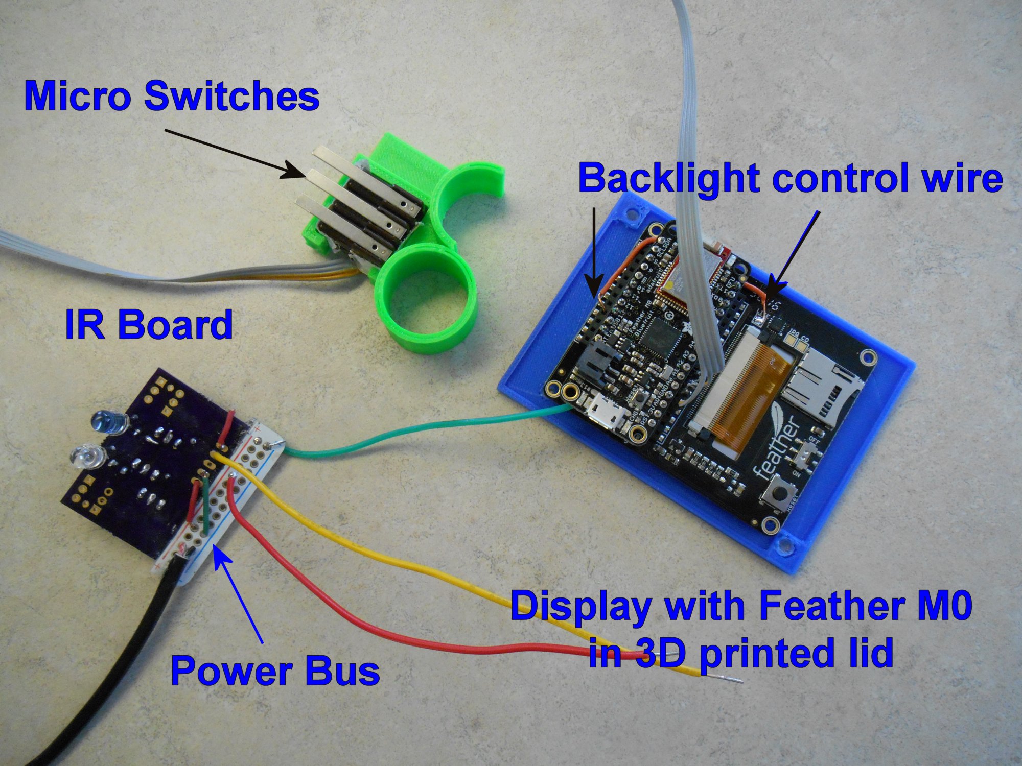
One of the nice things about the Feather Wing TFT board is that the feather board plugs into a socket in the backside. You don’t have to run wires from the main processor to the display board. However one of the disadvantages is that there is only one power and one ground pin on the device. So I was going to have to cut up a little piece of prototype board to make a power and a ground bus. This would bring in power from the outside, connected to the Feather and display boards, and run power to the infrared board. Similarly I needed ground wires to all of those parts plus a ground wire for the micro switches. We also needed to solder a jumper so that I can turn the backlight of the display off and on. There is a solder pad available but you have to jumper it to one of your Feather pins.
Although the Feather boards have a built-in battery connector and a battery charging circuit, I decided to power the device from an external 5v battery source. My old Ultimate Remote was a 5v device throughout while the Feather system runs on 3.3v. In the old system I had a short cable with a barrel jack running from the remote into a battery pack I call a Printy Boost. The Printy Boost is a device which I designed for the Adafruit Learning System as seen here. The Printy Boost also provides extended battery life to power my iPhone. So rather than have a separate battery for the remote and for the iPhone backup power I decided I would stick with the old system and run a cable from the Printy Boost into the remote just like I did before. Rather than connect to the +3.3v pin I connected to me “USB” pin which was the same as powering it through the USB cable at 5v.
There are some differences between the Feather TFT board and the old monochrome OLED graphics board so I had to tinker with the software to get things to run. Most of it was compatible because Most of the Boards operate on the Adafruit Graphics library but there are still differences. Once I had display software converted I tried using the device. Unfortunately it didn’t work again! You would think I would be more careful about crossed wires after the previous fiasco. It turns out we had the infrared I/O board wired backwards. I had drawn the wiring diagram looking at the front side of the IR board. That means on the right 2 pins are power and ground. Then moving to the left you skip one pin and the next one is the IR output. However the way the board is oriented in the device, the backside of the board is facing upwards. We wired it with power and ground on the right but that was wrong. Fortunately this just meant that the power lines were going to the receiver pins which were not being used in this application. So nothing burned out. We reversed the wiring and everything worked fine.
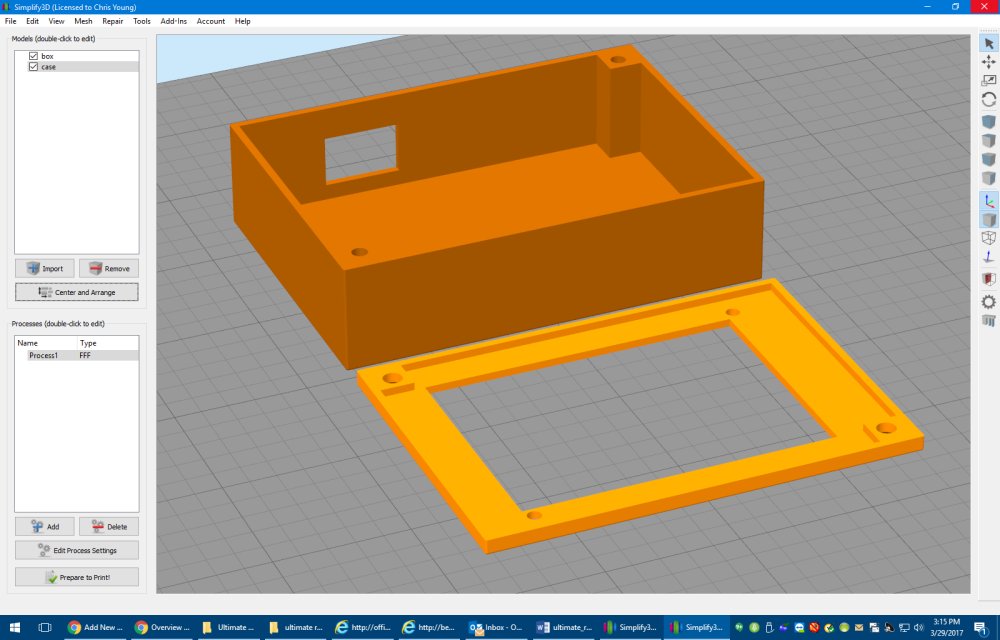
The final step was to design a 3D printed enclosure for the device. That took another afternoon or so.
We mounted the TFT display into the lid of the box using black nylon plastic screws and nuts out of this kit sold by Adafruit. They are really handy because they are selected to fit in the 0.1 inches diameter mounting holes used in most Adafruit boards. When that box of screws was first added to the Adafruit catalog I knew I would need them someday and purchased it right away. They work perfectly so it was a great purchase.
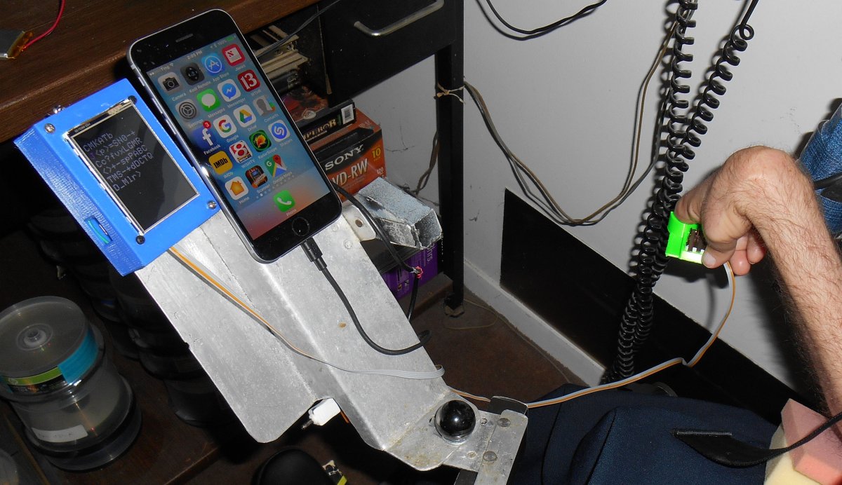
The rest of the box is held together by 5/8 inch sheet metal screws. I like using sheet metal screws because they have a pointy end that taps really well into 3D printed PLA plastic. Here are some more photos of the completed project.
There are still lots of software tweaks I have to implement. It takes longer to erase a 320×240 color display than it does to erase a 128×64 monochrome display. The monochrome device required you to call a “display” method to update the display after writing to it. The new color device updates as you write to it. The result is you can see the screen update where the old one would update instantly. I think the updates actually slow down the entire process a little bit. So I’m going to have to optimize the code so that it only updates the screen when absolutely necessary and only does it in small pieces. In the old system it was easy to just erase everything and redraw it from scratch every time but that won’t work very well in the new system.
Of course I also have to add all the features I’ve been wanting to add but didn’t have sufficient memory under the old system. I have to add all the codes for my Blu-ray player and there are some additional keyboard codes that I want to add. I may end up implementing an entire keyboard system so that I can type anything using IR codes. I’ve developed a special protocol for my IR library that allows me to use any mouse or keyboard commands possible. I’ve only been using a fraction of that capability.
One other difference between the old and new system involves the power output of the IR board. When I originally designed my infrared I/O board I ran the LEDs with no current limiting resistors. Because the LEDs are only intermittently running (assuming you don’t cross your wires), it’s safe to put more than 1 amp through them. But my experience is that sometimes USB power can’t supply enough power when that current spikes during transmission. So I’ve added some 33 ohms current limiting resistors in line with the LEDs on the latest version of my infrared I/O board. The old device did not have these resistors but it ran well because it was powered by a battery pack rather than a USB plug. Now that I’ve worked with the new remote I’m realizing it doesn’t have the power of the old one. I’m going to try shorting across those resistors and see if it helps.
I still have fond memories of my original Ultimate Remote. It served me well for over a year and was literarily a lifesaver while I was in the hospital. But I’m also looking forward to the new things I will be able to do with the new improved Ultimate Remote 2.0.
Afterward: After I completed the project I presented it on the weekly Adafruit Show-and-Tell. I was the first guest in the video below.
A few weeks ago we released IRLib 2.01 with preliminary support for SAMD 21 processors such as used in Arduino Zero and Adafruit Feather M0 boards. Then initial release had many hardcoded values. For example output was only available on pin 9 and the timer interrupt for the 50 µs receiver class was hardcoded to use TC3.
In our latest release IRLib 2.02 you now can use any available PWM pin on your platform for output by editing values in IRLibProtocols/IRLibSAMD21.h
You can now also choose to use TC4 or TC5 to drive the hardware interrupt for the 50 µs receiver class.
Both sending and receiving use GCLK0. Note that typically GCLK0-GCLK3 are reserved for internal Arduino infrastructure use however we are using GCLK0 with its default clock source of 48 MHz and a divisor of 1. Because we are not modifying those defaults, it is safe to use. That allows you complete freedom to use GCLK4-GCLK7 for other purposes.
The code has been tested on Arduino Zero, Arduino M0 Pro, and Adafruit Feather M0 BLE boards successfully.
We are pleased to announce a new version of IRLib library for receiving, decoded, and sending infrared signals using an Arduino. This represents months of work and is a major restructuring of the code to make it easier to include only those protocols that your application actually uses. Unfortunately the restructuring is so significant that it is not backwards compatible with our original IRLib1. It is however relatively easy to update your applications to use the new libraries. We will continue to leave IRLib 1.x in its original repository on GitHub. We have created a new repository https://github.com/cyborg5/IRLib2 for IRLib2. There will be no new updates to the original version of the code. Because we have changed the name to IRLib2 it is possible to have both versions available in your Arduino libraries folder at the same time without conflict.
Also included is a new feature called “auto resume” which ensures that you can continue receiving a second frame of data while processing the first frame.
The users manual has been expanded to 117 pages and not only includes the complete reference to all classes, methods, and variables that we had before, it also contains a new tutorial section which thoroughly explains all of the sample sketches. And finally we have the long-awaited tutorial on how to create new protocols for the library. You will also want to check out Appendix A which explains the changes between IRLib1 and IRLib2 as well as my rationale for the restructuring and the need to make it no longer backwards compatible.
The users manual is available in Microsoft Word, Adobe PDF, and EPUB formats in the GitHub repository. We will no longer be maintaining online HTML version of the documentation because it was too difficult to split into individual webpages and maintain it for this blog. However the supplied formats should be sufficient for all users.
Although we have thoroughly tested the code, it technically is version beta 0.1. If no major bugs are reported in a month or two we will upgrade it to official version 2.0 release.
We can’t wait to see what all of you will do with IRLib2. Please let us know how you are using the code.