IRLib Tutorial part 3d: Installing the Arduino IDE on a Raspberry Pi

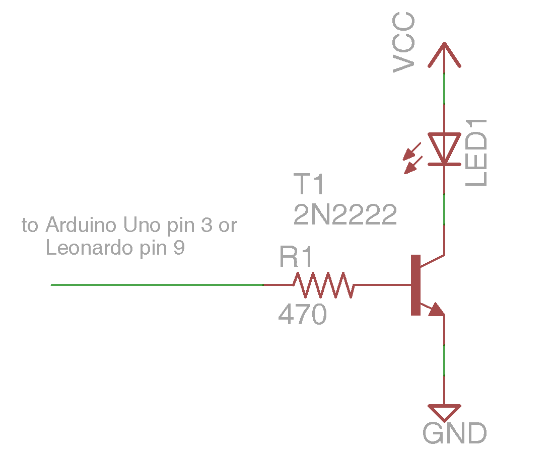
As we mentioned in part 3c, this section of the tutorial doesn’t have anything to do with IRLib specifically, however if you have not already installed the software necessary to run the tutorial part 3b then you will have to follow these instructions. In this section we will install the Arduino IDE on a Raspberry Pi. If you’re not using Raspberry Pi as a host machine but are using Windows like we did in part 3c then you do not need this tutorial at all.

Note: This article has only been tested with Arduino IDE version 1.0.x and not with the beta version 1.5.x. We cannot guarantee these procedures will work with the new version which may have a totally different structure since it is a fairly big upgrade.

We are assuming that you are using a plain vanilla Raspbian Wheezy OS on your Raspberry Pi. We cannot guarantee any of these instructions will work on other versions of the operating system. We are also assuming that your Raspberry Pi has Internet access for downloading updates. If your Raspberry Pi is not connected to the Internet you’ll have to figure out how to get the necessary files onto your system by an alternate means.

Raspbian Wheezy is actually a version of Debian Linux and according to the following reference http://playground.arduino.cc/Linux/Debian the Arduino IDE has already been prepackaged for easy installation. Go to a command prompt and type the following command
sudo apt-get install arduino
Breaking this command down for those of you who may not be familiar with Linux commands… The “sudo” stands for “Super User Do”. Access to the root directory and installation on your machine requires superuser privileges. This command temporarily gives you those privileges. And what are you going to do with them? You’re going to run the “apt-get” command. This is a system already set up in most Linux distributions to get various programs from a central repository. And the command that we passed this program is “install arduino”. I take the time to explain all of that because when I was new to Linux and didn’t know what I was doing, I would ask a question on the support forum and they would give me some obscure line of text type and I had absolutely no idea what I was doing or why.

This process not only installs the necessary Arduino components it also installs and/or updates various Java components necessary to run the Arduino IDE. If you do not have Internet access and did not use the “apt-get” command to install the package but simply copied the programs over to your Raspberry Pi, then you do not have the full package. The process of getting those additional Java packages is beyond the scope of this tutorial.

When the installation is completed most of the software is installed in the folder “/usr/share/arduino” and the folders inside that include “hardware”, “lib”, “libraries”, and “tools”. There is also an alias for the “examples” and “reference” folders however these folders are actually stored in “/usr/share/doc/arduino-core/”.

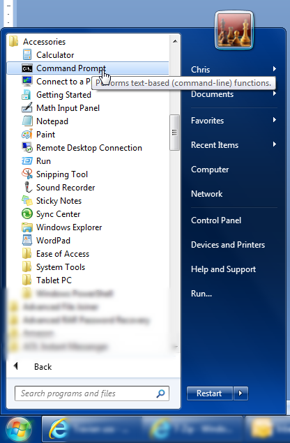
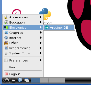
Also upon completion you will discover that your GUI start menu now has a new folder and it called “Electronics” which contains a link to the Arduino IDE as seen here.
startmenu
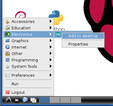
If you would like a shortstop on your desktop, the easiest way to do it is to collect up on the start but do not actually click on it. Instead do a right-click and there will be an opportunity to “Add to desktop” as seen here.
add2desktop
You now have an Arduino IDE shortcut on your desktop. For future reference your desktop icon is at /usr/share/pixmaps/arduino.xpm
icon
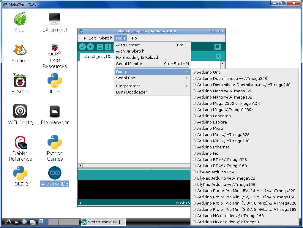
If you double-click on the desktop icon on select it from the start menu the Arduino IDE the first thing you will want to check is the version number. As of this writing the pre-packaged version of Arduino was only at version 1.0.1 however the most recent version was 1.0.4 which among other things added support for other Arduino boards such as the Arduino Esplora and Arduino Micro. If the above installation process did not get you the latest version then you will have to manually updated yourself. We successfully used the procedure below to update from 1.0.1 up to 1.0.4 and a week or so later ran the process again to get up to 1.0.5.

We’re going to assume you are starting out in a directory called “/home/pi” where “pi” is your username. If you’re logged in under a different username that will be different naturally. We recommend that you create a directory for downloading programs. At the command prompt type
mkdir downloads
Which obviously makes a directory called “downloads”. Then type…
cd downloads
Which changes your current directory to the downloads directory or folder. Then you should type the following command
wget http://arduino.googlecode.com/files/arduino-1.0.5-linux32.tgz
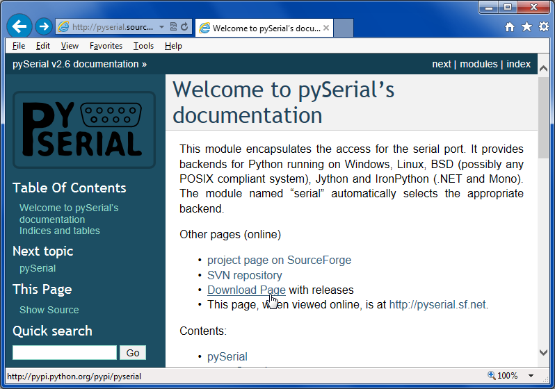
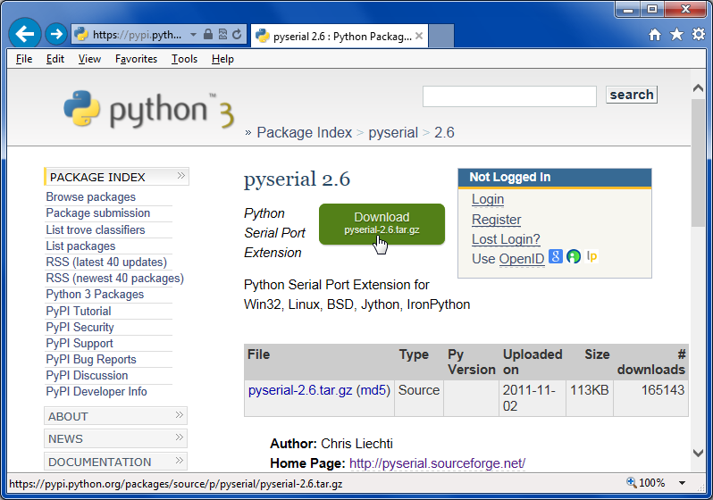
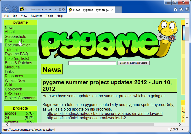
The “wget” command gets a file from the web. If you are installing something newer than 1.0.5 you will have to change the filename. If you are uncertain of the filename, call up a web browser in your computer and go to http://arduino.cc/en/Main/Software and then right-click on the 32-bit Linux link and copy shortcut. Then paste that text somewhere so that you can see the proper filename for the most recent version.

We will now use the “tar” utility to unzip the archive that we have downloaded. Issue the following command.
tar zxvf arduino-1.0.5-linux32.tgz
This will create a folder under your downloads folder called “arduino-1.0.5”. Then change to that folder with this command.
cd arduino-1.0.5
We now want to get rid of the “hardware/tools” folder inside the unzipped distribution. That is because the version that we have downloaded is compiled for an Intel x86 or AMD x86 processor and not the ARM chip that is in your Raspberry Pi. We will use the “rm” command to “remove” that folder.
rm -rf hardware/tools
Now we will copy using “cp” to copy the other files into their proper locations. We will go through the subfolders and overwrite any existing files.
cp -ru lib /usr/share/arduino
cp -ru libraries /usr/share/arduino
cp -ru tools /usr/share/arduino
cp -ru hardware /usr/share/arduino
cp -ru examples /usr/share/doc/arduino-core
cp -ru reference /usr/share/doc/arduino-core

Note some readers of this blog have reported that they needed to pre-append “sudo” to these commands above. If you are having difficulty with these commands you should try using “sudo cp -ru… etc.” instead.
Now if you launch the Arduino IDE you will see that the version has been updated. In this image we had only updated it to 1.0.4 but you can see it does have the additional boards that were missing from the 1.0.1 installation.
boards
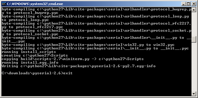
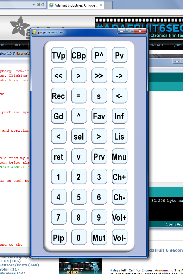
One last item… If you were doing this in order to run the IRLib tutorial part 3b on your Raspberry Pi then you will also need Python, PySerial, and Pygame. Fortunately Python and Pygame are already installed on your system. Be sure to use the Python 2 and not Python 3. You will however have to install the PySerial module with the following command.
sudo apt-get install python-serial
That should be all you need.

IRLib Tutorial part 3c: Python, PySerial and PyGame Installation on Windows

Although technically this installment of our tutorial isn’t directly related to IRLib, we are including it here as part 3c because it may be necessary to do these steps if you want to use the example in part 3b of our tutorials.

We’re going to take you step-by-step through installing Python and other necessary modules on a Windows system. We used this method on a Windows 7 64-bit home premium PC. Other versions of Windows will have extremely similar installations.

In order to use the previous examples, we highly recommend that you use Python 2 rather than Python 3 and we recommend that you use the 32-bit version even if you are on a 64-bit Windows machine. You might be able to get our examples to work under 64 bits or Python 3 but we were warned there might be problems and we did encounter them and chose not to try to come up with workarounds.

 Installing the Python Interpreter

Python is an interpreted language rather than a compiled language. The Python interpreter is a program that runs on your PC, reads the text script of your Python program and executes the script rather than compiling it into native machine language for your type of hardware. You can download the Windows version of Python 2 or 3 at…

http://www.python.org/download/releases/

As of this writing the most recent version of Python 2 is 2.7.5 dated May 15, 2013. Download the file named “Windows x86 MSI Installer (2.7.5) (sig)” you can save the program and run it from the same location or run it immediately.

01 downloadInstall the program for all users.

02 all usersChoose your directory. The default will work.03 directory

The default for customization is install everything. That will work fine.

04 customize

And complete the installation

04 finishWhen you completed the installation the following items will be in your start menu.

06 start menuThere is a command line version that can run scripts directly or there is an IDE called “IDLE”. In our previous installment of the tutorial we use the IDE.

There is one more item we need to do to complete this installation. We need to add the Python interpreter to the default system path so that when you try to execute a Python script it will know where to find the interpreter. The process is slightly different on Windows XP versus Windows Vista, 7, or 8.

 Adjusting the path on Windows Vista, 7, or 8…

Go to your Control Panel and click on “System”. If you are in icon view you can click on “System” directly. If you are in category view you should click on “System and Security” and then click on “System”. You should next click on “Change Settings” as shown here

07 change settingsYou will get a system properties dialog that looks like this. You should click on the “Advanced” tab.

08 system propertiesNext click on environment variables.

09 advancedYou’ll get the Environment Variables dialog which looks like this.

In the upper section look for the item “Path”. Select it and click on “Edit” just below it.

11 pathThen very carefully go to the end of the variable value and add a semicolon followed by the path where you installed Python. Make sure do not erase any other text that was previously there. On my system I added “;C:\Python22” to the end of the value. Then click on okay and continue out of all of the open dialogues. You can now proceed to the next section where we will install pySerial.

Adjusting the path on Windows XP

Go to your Control Panel and click on “System”. If you are in classic icon view you can click on “System” directly. If you are in category view you should click on “Performance and Maintenance” and then click on “System”. Unlike later versions of Windows, this will take you directly to the “System Properties” dialog. You do not need to click on any “Change Settings” link. It will look like this…

08 system properties XPClick on the tab labeled “Advanced” and it will look like this

09 advanced XPClick on the “Environment Variables” button and you will see the following dialogue.

10 environment variables XPIn the lower section look for the item “Path”. Select it and click on “Edit” just below it.

11 path XPThen very carefully go to the end of the variable value and add a semicolon followed by the path where you installed Python. Make sure you do not erase any other text that was previously there. On my system I added “;C:\Python22” to the end of the value. Then click on okay and continue out of all of the open dialogues. You can now proceed to the next section where we will install pySerial.

Installing PySerial

Next we will install the PySerial module which will allow us to do serial communication through Python. The main page for the PySerial code is…

http://pyserial.sourceforge.net/

Click on the “Download Page” link as shown here
20 pySerialAt click on the big green download button. Save the file to a convenient location. Note that the version “2.6” refers to the pySerial version and not to the version of Python which you are running.

21 downloadUnzip the file. If you do not have a utility that can handle .tar.gz compressed files we recommend using “7 Zip” which can be downloaded here…

http://www.7-zip.org/

Now we will have to do something that Windows users rarely do. We need to type some command lines to install the package. Click on your start button and choose the “run” command and then type “cmd”.
22 run command
23 run dialog cmd

Or alternatively you may have a command prompt shortcut in your start menu under accessories as shown here.
24 command prompt

When the command line window comes up you need to change directories to where you unzipped the pySerial package. In my case it was in the c:\downloads\pyserial-2.6 so the command was…

cd c:\downloads\pyserial- 2.6

Then type the following command…

python setup.py install

25 set up install

When the installation is complete type “exit”
26 exit

 Instructions for Installing Pygame

Our final step is to install the Pygame package. You can download it at

http://www.pygame.org/

Click on the download link in the upper left menu

30 pygame

Scroll down to the section for windows and click on the link labeled “pygame-1.9.1.win32-py2.7.msi”
31 download

Or whatever the most recent 32-bit Windows installer link is. Simply run the installer and use all of the default settings to complete installation.

That’s everything you need to know to install Python, PySerial and Pygame on a Windows machine.

If you are using a Raspberry Pi you will already have Python and Pygame installed with the standard version of Raspbian. To install PySerial simply go to a command prompt and type

sudo apt-get install python-serial

This tells it to issue a superuser command to get the package and install it. In the next installment of this tutorial we will talk about how to install the Arduino IDE on a Raspberry Pi.

IRLib Tutorial part 3b: Creating a Virtual Remote Using Python

satb100In the previous lesson we demonstrated how to send IR codes to a TV, DVD, DVR/cable box or any other device that uses an infrared remote. In order to tell the Arduino what code to send, we typed codes into the serial monitor of the Arduino IDE. While that’s great for demonstration purposes, it’s not very practical. In this continuation of the lesson, we will create a small program using Python which will create a “virtual remote”. This Python script will run on your PC, laptop or even Raspberry Pi which is connected to the Arduino. As you click on the buttons on the app, the script will send the proper codes over the serial link to the Arduino. The Arduino in turn will send the IR signals to your device. In addition to the items listed in part 3a will also need…

  • a PC, laptop or even a Raspberry Pi with the Arduino connected to a USB port.
  • Python 2.x programming environment installed
  • PySerial add-on for Python that enables serial communication
  • PyGame add-on for Python that makes it easy to use graphics, mouse, keyboard
  • IRLib version 1.1 or later which includes the sample code

  • At the end of this tutorial we will post links to the Python, PySerial and PyGame packages. In part 3c of this tutorial we will give detailed instructions on how to install these passages on a Windows PC and a Raspberry Pi. When using Raspberry Pi it will probably already have Python and probably PyGame installed or you can find instructions on how to install them elsewhere online. We will include instructions on installing PySerial, the Arduino IDE and the IRLib packages on Raspberry Pi.

    This example assumes you are using Python 2.7.x or later. Python 3 has some problems with serial communication especially in the Windows version. We also highly recommend installing the 32-bit version even if you have a 64-bit computer. We cannot guarantee this will run on 64 bits. Similarly when installing PySerial we recommend the 32-bit version.

    Presuming you already have these packages installed we can proceed to customize a Python script to create virtual remote. In the previous installment we had you use the dump routine on your Arduino to capture the protocols, codes and number of bits for the functions you want to use. Our Python app can handle up to 40 functions however you can leave some of the buttons empty if you wish. But if you’re not yet done so, go back to the previous lesson and write down a whole bunch of codes you want to put in this new remote.

    The Python script we will use is available in IRLib/examples/IRserial_remote/IRserial_remote.py. You also need the files “click.wav” and “remotebg.png” in the same folder. You will have to edit several lines of the script to customize it for your purposes.

    A few lines into the script we will have to edit the serial port that the script we use to communicate to the Arduino. Look for these lines…


    # You will have to edit this to the proper port and speed
    ser = serial.Serial('COM4', 9600)

    As distributed it is set to “COM4” but on a PC it might be some other COM port or on a Linux machine such as a Raspberry Pi it would be something like

    ser = serial.Serial('/dev/ttyACM0', 9600)

    We also need to specify what font will be used to put the labels on the buttons a few lines down like this…


    # Specify a font. I'm using Arial narrow bold from my Windows
    # font folder. However the default font shown below also works.
    myfont =pygame.font.Font ("c:/windows/fonts/ARIALNB.TTF",30)
    #myfont=pygame.font.Font(None,36)

    By the way if you are not familiar with the Python language it uses a hash tag at the beginning of the line to specify it is a comment. The default is a Windows font that is Arial narrow bold that you can specify your own font of choice or used default font by substituting the word “None” as shown above. Look for the section where we define the label text each button. Here are the values as distributed.

    # These are the text labels that will appear on each button
    label_text=("TVp", "CBp", "P^", "Pv",
    "<<", ">", ">>", "->",
    "Rec", "=", "s", "<-", "Gd", "^", "Fav", "Inf", "<", "sel", ">", "Lis",
    "ret", "v", "Prv", "Mnu",
    "1", "2", "3", "Ch+",

    "4", "5", "6", "Ch-",
    "7", "8", "9", "Vol+",
    "Pip", "0", "Mut", "Vol-",
    )

    These correspond to TV power, cable box power, Page Up, Page Down, rewind, play, fast-forward, jump to live, record, pause stop, jump back, Up Arrow, favorites, info, Left Arrow, Select, Right Arrow, Lists Recordings, Return, Down Arrow, Previous Channel, Menu, numbers 1 through 9 and 0, Channel up, Channel down, Volume up, Volume Down, Mute, and PIP. However you can make them say anything you want.

    Below that we insert the actual codes. We will use the same format we used in the previous lesson when we type codes into the serial monitor. First is a single digit that describes the protocol number, followed by a hex value, followed by the number of bits. Note that when some protocols the number of bits is optional. Here are the codes I used for a Magnavox TV using the “RC5” protocol and 13 bids And a Scientific Atlantic SA 8300 DVR using the PANASONIC_OLD protocols.


    IR_Codes= ("3,180c,13","5,37c107","5,36d924","5,37d904",
    "5,37291a","5,37990c","5,36293a","5,36b129",
    "5,375914","5,374117","5,365934","5,37c906",
    "5,36c127","5,36812f","5,37f101","5,36213b",

    "5,37810f","5,366133","5,364137","5,36c926",
    "5,366932","5,37a10b","5,36e123","5,373918",
    "5,36113d","5,37111d","5,36912d","5,377111",

    "5,37910d","5,365135","5,375115","5,36f121",
    "5,36d125","5,37d105","5,363139","3,1810,13",
    "5,37b908","5,373119","3,180d,13","3,1811,13",
    )

    Once you have everything edited using your codes you should then load the IRserial_remote sketch into your Arduino. You can try typing a few codes into the serial monitor to make sure it’s working but once you are sure the sketch is running properly you need to close the serial monitor and the Arduino IDE so that they do not tie up the serial port. If you do not close at least the serial monitor, your Python script may not be able to connect to the Arduino properly.

    Then run the Python script IRserial_remote.py script. A window should pop up showing a virtual remote control with 40 buttons on it looking something like this…

    Virtual TV Remote using Python

    Virtual TV Remote using Python


    Notice as you hover your mouse over each button, the text will turn red. If you click on the button with the mouse it will make a clicking noise and it will instruct the Arduino send the proper IR codes. If everything works properly you should be able to control your device. Here is a YouTube video demonstrating how it works.

    It’s not our intent to make this a Python tutorial so we will not go through the Python script line by line to explain how it works. Also included in the examples folder under IRserial_remote is a folder called “povray” which contains the source file for the Persistence of Vision Ray Tracer POV-Ray which is a freeware rendering program which was used to create the background image for the buttons on the remote.

    Here is a video which demonstrates this application. This video was shown on the weekly Adafruit Show and Tell video chat on Google+ You can click on the “As seen on Show-and-Tell” logo at the top of this post to see it on the show and tell.

    As promised here are links to various downloads you may need for this tutorial

    In the next installment we will show you how to install these packages in case you haven’t already done so.

IRLib Tutorial part 3a: Sending IR Codes

In this lesson we will demonstrate how to send IR codes to a TV, DVD, DVR/cable box or any other device that uses an infrared remote. You will need…

  • a 38 kHz IR receiver module,
  • an IR LED and driver circuit such as described in part 1 of this tutorial,
  • a TV, DVD, DVR or whatever device to control,
  • an IR remote control for that device so we can obtain the proper codes.

Begin the process by wiring an IR receiver to pin number 11 on your Arduino as described in part 1 of this tutorial. Hook up an IR LED and a driver circuit also described in part 1 of this tutorial. If you are using Arduino Uno it will connect to pin 3. On the Arduino Leonardo you should use pin 9

Now you should load the IRrecvDump sketch from the examples folder of the IRLib library. We will use this sketch to determine what codes your infrared remote is transmitting. Run the sketch and open the serial monitor. This is the same process described in part 2 of this tutorial. Write down the received codes for all of the major functions of your device such as power on, channel up and down, volume up and down, rewind, fast-forward, play, stop etc. Also make note of the protocol and the number of bits. Here is what the dump for the power on function looks like on my Magnavox TV
Decoded RC5: Value:180C (13 bits)
Raw samples(24): Gap:30014
Head: m850 s900
0:m900 s900 1:m1700 s900 2:m900 s900 3:m850 s900
4:m850 s900 5:m850 s900 6:m900 s850 7:m900 s1750
8:m900 s850 9:m1750 s900 10:m900
Mark min:850 max:1750
Space min:850 max:1750

As before, you only need to concern yourself with the first line of text. The protocol is “RC5” the code is “180C” and it uses 13 bits.

We are going to presume that you are using a remote that has a protocol that this library understands. If the top line of the dump says “Decoded Unknown” then you will have to skip ahead to section on how to program your own protocol in a future lesson of this tutorial.

Now load the following sketch named “IR_serial_remote” which is shown here. It is also available in the latest update to IRLib version 1.1 which was uploaded to GitHub on April 21, 2013 or later. This upgrade to the library also contains some other minor enhancements and a copy of the “IRservo” example used in part 2 of this tutorial.
#include

IRsend My_Sender;

int protocol;
long code;
int bits;
void setup() {
Serial.begin(9600);
}

long parseHex (void) {
long Value=0; char C;delay(100);
while (Serial.available()>0) {
C= tolower(Serial.read());
if ((C>='0')&&(C<='9')) C=C-'0'; else if ((C>='a') && (C<='f')) C=C-'a'+10; else return Value; Value= C+(Value<<4); }; return Value; } void parseDelimiter () { char C; while(Serial.available()>0) {
C=tolower(Serial.peek());
if( (C>='0') && (C<='9') )return; if( (C>='a') && (C<='f') )return; C=Serial.read();//throwaway delimiters delay (5); } } // enum IRTYPES {UNKNOWN, NEC, SONY, RC5, RC6, PANASONIC_OLD, JVC, NECX, HASH_CODE, LAST_PROTOCOL=HASH_CODE}; void loop() { if (Serial.available ()>0) {
protocol = Serial.parseInt (); parseDelimiter();
code = parseHex (); parseDelimiter();
bits = Serial.parseInt (); parseDelimiter();
/* Serial.print("Prot:"); Serial.print(protocol);
Serial.print(" Code:"); Serial.print(code,HEX);
Serial.print(" Bits:"); Serial.println(bits);
*/
My_Sender.send(IRTYPES(protocol), code, bits);
}
}

Upload the sketch and open the serial monitor. We will type in the protocol number, function code, and the number of bits for one of the functions that you wrote down. For example to turn on my TV I would type in

3,180c,13

The “3” is the number of the protocol that I’m using. If you look in “IRLib.h” at about line 50 you will see the following enum definition.

enum IRTYPES {UNKNOWN, NEC, SONY, RC5, RC6,
PANASONIC_OLD, JVC, NECX, HASH_CODE,
LAST_PROTOCOL=HASH_CODE};

You can send that “RC5” is the third protocol. In my examples I will also be using protocol 5 which is “PANASONIC_OLD” which is the protocol used by my Scientific Atlantic SA 8300 HD cable box/DVR.

After typing in the protocol number, code, and number of bits in the serial monitor you should press enter or click on the “send” button. The Arduino should decode this information and send the proper signals from your IR LED. If you want to make sure that what you are typing is getting parsed you can uncomment the “Serial.print…” statements near the end of the sketch.

Here are the details on how the sketch works…

We start by including the IRLib.h file for the library. We create the sender object and create some integers to store the protocol number, code, and number of bits. The setup routine simply initializes the serial port.

The standard Serial objects include routines for parsing integers in decimal format coming across the serial line but it does not include parsing hexadecimal values so we’ve written a little routine called

long parseHex (void)

Which accepts characters “0” through “9” and “A” through “F” either upper or lower case and converts it into an integer value. We also have a routine called

void parseDelimiter ()

It skips over any commas, blanks or other extraneous characters which you use as a separator.

The main loop simply looks for serial characters available, parses them, and then sends them using the send method as follows

My_Sender.send(IRTYPES(protocol), code, bits);

Note that because the protocol is actually an enum rather than an integer we have to typecast it when passing it to the send method.

Of course it would be quite tedious to have to look up the protocol number, hex codes, and number of bits every time you wanted to send a function. So we’re going to write a program which will send that serial data from your PC to the Arduino. We will create a “virtual remote control” in which you can click on buttons on it will send that serial data to the Arduino which will in turn control your device.

In part 3b we will show you how to use a Python script to create just such a virtual remote and send the codes from your PC or laptop to the Arduino.

IRLib Tutorial part 2: Controlling a Servo Using an IR Remote

As seen on Show-and-TellIn this lesson we will demonstrate how to receive IR codes and to use that information to do something useful. In this case we’re going to position a servo. You will need

  • a 38 kHz IR receiver module
  • a servo motor that uses PWM for positioning
  • an IR remote control for a TV or VCR or any such device

At the end of this blog we will link to some sources for these items. If you do not have a servo available you should be able to follow the code given here to control relays or turn on and off LEDs or any other function you might control with an Arduino microcontroller.
Begin the process by wiring an IR receiver to pin number 11 on your Arduino as described in Lesson 1 of this tutorial. For this example you do not need to hook up an IR LED. We’re going to be receiving only. Also hook up a servo motor to power and ground and to pin number 9 on your Arduino. This diagram shows the complete set up.

Hardware set up for IR servo control demo

Hardware set up for IR servo control demo


Now you should load the IRrecvDump sketch from the examples folder of the IRLib library. We will use this sketch to determine what codes your infrared remote is transmitting. Run the sketch and open the serial monitor. Point your remote at the receiver and press the right arrow button. In this example I’m using a remote from my Sony DVD/VCR. The output on the serial monitor looks like this…

Decoded Sony: Value:86BCA (20 bits)
Raw samples(42): Gap:12550
  Head: m2300  s650
0:m1200 s600 1:m550 s650  2:m550 s650 3:m500 s650
4:m550 s650 5:m1150 s650  6:m1150 s600 7:m600 s600
8:m1150 s650 9:m550 s650  10:m1100 s650 11:m1200 s600
12:m1150 s650 13:m1150 s600  14:m550 s650 15:m550 s650
16:m1150 s650 17:m550 s600  18:m1200 s600 19:m550
Mark  min:500  max:1200
Space min:600  max:650 

We really only need to concern ourselves with the first line of text of this dump. It says that the protocol that was decoded was “Sony” and that the value was 86BCA which is a number in hexadecimal code. The remainder of the information is unimportant to us. You need to write down the value received for each of the following buttons: right arrow, left arrow, up arrow, down arrow, select, and the number buttons 0 through 9.
We are going to presume that you are using a remote that has a protocol that this library understands. If the top line of the dump says “Decoded Unknown” then you either need to use a different remote or skip ahead to section on how to program your own protocol in a future lesson of this tutorial.
Now load the following sketch named “IR_Servo” and we will modify it with the codes you have obtained. You can click on the little orange pair of scissors to copy the code into your clipboard.

/* Example program for from IRLib – an Arduino library for infrared encoding and decoding
 * Version 1.0  April 2013 by Chris Young http://cyborg5.com
 * "IR_Servo" Control a servo using an IR remote
 */
#include <IRLib.h>
#include <Servo.h> 
// You will have to set these values depending on the protocol
// and remote codes that you are using. These are from my Sony DVD/VCR
#define MY_PROTOCOL SONY
#define RIGHT_ARROW   0x86bca //Move several clockwise
#define LEFT_ARROW    0x46bca //Move servo counterclockwise
#define SELECT_BUTTON 0xd0bca //Center the servo
#define UP_ARROW      0x42bca //Increased number of degrees servo moves
#define DOWN_ARROW    0xc2bca //Decrease number of degrees servo moves
#define BUTTON_0 0x90bca  //Pushing buttons 0-9 moves to fix positions
#define BUTTON_1 0x00bca  // each 20 degrees greater
#define BUTTON_2 0x80bca
#define BUTTON_3 0x40bca
#define BUTTON_4 0xc0bca
#define BUTTON_5 0x20bca
#define BUTTON_6 0xa0bca
#define BUTTON_7 0x60bca
#define BUTTON_8 0xe0bca
#define BUTTON_9 0x10bca
IRrecv My_Receiver(11);//Receive on pin 11
IRdecode My_Decoder; 
Servo My_Servo;  // create servo object to control a servo 
int pos;         // variable to store the servo position 
int Speed;       // Number of degrees to move each time a left/right button is pressed
 
void setup() 
{ 
  My_Servo.attach(9);  // attaches the servo on pin 9 to the servo object 
  pos = 90;            // start at midpoint 90 degrees
  Speed = 3;           //servo moves 3 degrees each time left/right is pushed
  My_Servo.write(pos); // Set initial position
  My_Receiver.enableIRIn(); // Start the receiver
} 
 
void loop() 
{ 
    if (My_Receiver.GetResults(&My_Decoder)) {
       My_Decoder.decode();
       if(My_Decoder.decode_type==MY_PROTOCOL) {
          switch(My_Decoder.value) {
            case LEFT_ARROW:    pos=min(180,pos+Speed); break;
            case RIGHT_ARROW:   pos=max(0,pos-Speed); break;
            case SELECT_BUTTON: pos=90; break;
            case UP_ARROW:      Speed=min(10, Speed+1); break;
            case DOWN_ARROW:    Speed=max(1, Speed-1); break;
            case BUTTON_0:      pos=0*20; break;
            case BUTTON_1:      pos=1*20; break;
            case BUTTON_2:      pos=2*20; break;
            case BUTTON_3:      pos=3*20; break;
            case BUTTON_4:      pos=4*20; break;
            case BUTTON_5:      pos=5*20; break;
            case BUTTON_6:      pos=6*20; break;
            case BUTTON_7:      pos=7*20; break;
            case BUTTON_8:      pos=8*20; break;
            case BUTTON_9:      pos=9*20; break;
          }
        My_Servo.write(pos); // tell servo to go to position in variable 'pos' 
       }
     My_Receiver.resume();
    }
}

First you need to tell it what protocol you have received. Edit it into the line which reads

#define MY_PROTOCOL SONY

In general want to use the protocol name that was shown in the dump routine but it must be in all capital letters. If you want to get technical about it, legal values for this item are shown in the file “IRLib.h” at approximately line 53 which looks like this.

enum IRTYPES {UNKNOWN, NEC, SONY, RC5, RC6, 
  PANASONIC_OLD, JVC, NECX, HASH_CODE, 
  LAST_PROTOCOL=HASH_CODE};

Now back to the sketch… You need to edit into the sketch the values which you copied down for each of your buttons on your remote. Note that since these are hexadecimal numbers you should precede each one with “0x”. So in our example for the right arrow which produced a value of “86BCA” the line should look like this…

#define RIGHT_ARROW   0x86BCA

Note that in hexadecimal numbers when the letters “A” through “F” are used you may use either upper or lower case letters.
Once you have all of the values edited into the sketch, you should upload it. The servo will automatically center itself when the sketch has been uploaded and runs. Point your remote at the IR receiver and press the right or left arrow on your remote. The servo should rotate right or left as you push the buttons. If you push the select button on your remote it should center of the servo again. Pressing the numbers 0 through 9 will position the servo to fixed points 20 degrees apart.
By default, when using the left and right arrow buttons, the servo will rotate left or right by 3 degrees for each push of the button. By using the up arrow or down arrow buttons you can change how far the servo rotates. If you press and hold the down arrow for a couple of seconds it will change the default rotation to 1 degree. Pressing the up arrow button increases it to a maximum of 10 degrees. You won’t see anything happen when you push up or down but subsequent presses of left or right will be faster or slower. Here is a YouTube video demonstrating the project.

Now let’s look at the sketch line by line to see how it works. Just below the section which you edited we define several variables and objects

IRrecv My_Receiver(11);//Receive on pin 11
IRdecode My_Decoder; 
Servo My_Servo;  // create servo object to control a servo 
int pos;         // variable to store the servo position 
int Speed;       // Number of degrees to move each time a left/right button is pressed

We create a receiver object and tell it to look for codes on pin 11. IR codes consist of a series of on and off signals called marks and spaces. The receiver object is an interrupt driven routine that looks for a signal every 50µs. It then stores in a buffer of integers the length of each mark or space in 50µs intervals. The buffer is located in the decoder object so we pass the address of the decoder to the receiver. There are technical reasons why we have separated these processes into receiver and decoder unlike other IR libraries. We will get into that in a future must. As mentioned we also have to create a decoder object. The decoder object looks at the values and attempts to determine which protocol was used and what the data values are that were encoded in the signal. We also create a servo object. Details on the servo library can be found here in the standard Arduino documentation. And we need integers to hold the position and the speed of the servo.
In the “Setup” function we initialize the servo on pin 9 set some default values and give it the command to move the servo into the default position. You then have to use this line

  My_Receiver.enableIRIn(); // Start the receiver

To initialize the IR receiver. In the “Loop” routine we have a single if statement that is constantly looking for an IR code.

    if (My_Receiver.GetResults(&My_Decoder)) {
       My_Decoder.decode();

The “GetResults(address)” function returns true if a code has been received. It puts it into the decoder object whose address you passed to it. You then call the “decode()” method of your decoder.
We next check to see if the results received were from the proper protocol. No need to go through a bunch of testing if you picked up a signal from a different remote. We check to see if the “decode_type” is the right one using this if statement. The variable “My_Decoder.decode_type” is an enum which was shown earlier in this lesson and can be found in “IRLib.h”.

       if(My_Decoder.decode_type==MY_PROTOCOL) {

Finally we check the “My_Decoder.value” in a switch statement to see if any of our defined codes are what was sent. If none of the case statements are activated, the code just falls through and updates the servo at its previous position.
It is important that we restart the IR receiver after any signal has been received even if it’s not one that we were interested in. This is done with the following statement

     My_Receiver.resume();

You could easily modify the sketch to handle multiple servos doing all sorts of things such as positioning a robot arm or steering a remote-controlled car or doing any other function. You could hook up LEDs that would turn off on depending on which button to press on the remote. You could hook up relays to turn lights on motors off and on.
As promised here are some links to the hardware mentioned in this post

In the next lesson we will focus on transmitting IR signals.

IRLib Tutorial part 1: Hardware set up

This is the first in series of articles on using my infrared remote library for Arduino. In this installment we’re going to show you how to set up the hardware and how to run a quick demo sketch. You can find out more about the library on my IRLib page.

In order to detect a single from IR remote control such as you might use for your TV or home entertainment system you need an IR receiver module. Typically I use a unit I get from Radio Shack. You can also buy a similar module from my favorite supplier Adafruit.com. See the links at the end of this post for places where you can buy all of the parts mentioned in this article.

Pin 1 (on the left as you looking at the lens) needs to be connected to a input pin of the Arduino. It can be any could be any pin that doesn’t conflict with anything else you’re doing with the device. All of the examples in the library assume you are connected to pin 11 so we suggest you use it. The center pin 2 connects to ground any right-hand pin 3 should connect to your +5V power supply. If you are using a different microcontroller that runs at +3V this device will work at that voltage.

The simplest output device is simply an infrared LED and a current limiting resistor. IR LEDs can be purchased from a variety of places. Again see the links at the bottom of this post for sources. You are limited to using PWM pins for output because we use the PWM feature to modulate the signal. The default pin to use on Arduino Uno or other ATmega328-based controllers is pin 3. This particular pin is connected to “timer 2” of the chip. However the Arduino Leonardo and other controllers based on the ATmega32u4 does not have a “timer 2”. On these devices the default is to use timer 1 and pin 9 for output. We will talk more later about other options for timers and how to use this library on other types of hardware. For now all you need to know is if you have an Uno you should use pin 3 or a Leonardo use pin 11. Connect a 100 ohm resistor in series with the LED. Make sure you get the polarity of the LED correct. The shorter of the two leads should connect to ground. The longer lead connects to the resistor which in turn connects to the Arduino. Here is a schematic for the simplest setup. Note this post was edited on 2/5/2014 to correct the polarity. After telling you to be sure to get it right, I had described it wrong. The schematic has always been correct but my description was wrong. Sorry about that.

Simple IR I/O Schematic

Simple IR I/O Schematic

That was the absolute simplest schematic however the output from the IR LED will be pretty weak because the output pins of Arduino cannot supply much current. You might want to consider adding an NPN transistor to drive the LED.

NPN Transistor Driving IR LED

NPN Transistor Driving IR LED

Here is a schematic using a PN2222 NPN transistor and a 470 ohm base resistor with the LED. WARNING: This circuit will drive the LED beyond its continuous current limits of 100 mA. However because we are only pulsing the LED for a brief period using a modulated signal we can get away with this. So you should only use the circuit if you are certain that the output pin is not going to be left on continuously for more than a fraction of a second.

Here is a simple sketch you can use to test if you are receiving IR signals. Is a stripped down version of the example sketch “IRrecvDump” that is in the examples subdirectory of the library.

/* Receiving IR signal and dump the details */
#include
//create a receiver object
IRrecv My_Receiver(11);//Use input pin 11

//create a decoder object
IRdecode My_Decoder;
void setup()
{
Serial.begin(9600);//We will read the output on the serial monitor
My_Receiver.enableIRIn(); // Start the receiver
}
void loop() {
//Loop until we get a signal and pass it to the decoder
if (My_Receiver.GetResults(&My_Decoder)) {
My_Decoder.decode();//decode the signal
My_Decoder.DumpResults();//dump the results on the serial monitor
My_Receiver.resume(); //restart the receiver
}
}

Upload the sketch and start the serial monitor on the Arduino IDE. Point a remote control such as a TV remote at the receiver and press a button. It will dump the information about the signal received. If it’s a protocol with the library understands it will tell you which protocol and it will give you a hex number of up to 32 bits that is the code for that particular function.

To test your transmitter, first determine the 32 bit hex code and protocol that the library can decode. A good example would be the power off/on button of your device assuming that your protocol is supported. As an example I sent a power signal to my Sony DVD player. The dump program tells me that it is a 20 bit code that is Sony protocol and that the value is 0xa8bca. The following sketch is a version of the example “IRsendDemo” in the examples directory of the library.

/*Transmit a power code for Sony DVD*/
#include

IRsend My_Sender;
void setup()
{
Serial.begin(9600);
}
void loop() {
if (Serial.read() != -1) {
//send a code every time a character is
//received from the serial port
//Sony DVD power A8BCA
My_Sender.send(SONY,0xa8bca, 20);
}
}

You will need to substitute the protocol name, the hexadecimal code, and the number of bits for whatever device you are operating. After you upload the sketch type a character into the serial monitor and press enter. Every time you transmit a character from the serial monitor, it will transmit the code you have programmed into the “My_Sender.send(…)” Function call.

In the installments which follow we will explain more of the details of the library including a more advanced circuit for transmitting codes. However for now this should get you up and running.

As promised here are some links to the hardware mentioned in this post

In the next installment will show how to receive and decode IR signals and use them to do something useful such as control a servo.

Announcing a New Infrared Remote Control Library for Arduino

In April 2012 I begin work on a project to create an infrared remote control using an Arduino Uno. I downloaded a library of code called IRremote which was published by Ken Shirriff in his blog post here.
http://www.righto.com/2009/08/multi-protocol-infrared-remote-library.html
His library is available on github.com at https://github.com/shirriff/Arduino-IRremote
It’s a remarkable piece of work that makes it incredibly easy to receive, decode, and transmit IR signals such as are used for TVs and other consumer electronics. It supported NEC, Sony, RC5 and RC6 protocols as well as a raw data mode and he later added a 32-bit hash code version. Note: so I don’t have to remember constantly have to spell “Shirriff” I’m going to refer to his original library as the KS library.

However I needed to add some additional protocols of my own. It took a lot of research from a variety of sites but I eventually found a pair of websites that will especially useful in helping me to understand the various protocols available.

One especially useful site is this one which I believe KS cites in his blog http://www.sbprojects.com/knowledge/ir/index.php

However the one that had the most information is this one http://www.hifi-remote.com/johnsfine/DecodeIR.html

It uses a notation called IRP notation that is insanely difficult to understand but once you do it is a very concise way of describing an IR protocol. I used that reference to determine that my Bright House cable boxes which are either Scientific-Atlanta or Cisco user protocol called “Panasonic old”. It also helped me identify NECx and Samsung36 protocols which I needed to implement for various devices I have.

After after adding several of these protocols to the original KS library I realize there was a lot of redundant code being created. Also the way it was written you either had to use all of the protocols at once or you had to create your own custom version in which you deleted or commented out the protocols you didn’t need. Although the code was written in C++ it really didn’t take advantage of object-oriented programming practices for which this application was especially suited. What we really needed was a variety of decoder objects based upon a base object that could be extended by additional protocols without having to modify or recompile the original library.

Also found it a bit difficult to understand what part of the code was hardware related dealing with timers and interrupts and PWM signals versus the encoding and decoding of protocols. Once you understand the protocols you really don’t need to know the hardware specifics. In many ways that’s the whole purpose of a library is to make things as “black box” as possible. The user doesn’t need to know the internal details, only the program interface.

For my own deeper understanding of the code and as a programming exercise I embarked upon a almost complete rewrite of the entire library using the principles of object-oriented programming. I am now ready to release my rewritten library on github for others to use. I did not created as a fork of the original KS library because the rewrite is so extensive that it really doesn’t work as a patch to the original code. I’ve also renamed it because it isn’t really very backward-compatible with the previous code at least from a software standpoint. If you have hardware configured for the previous library it should work out of the box with this library.

I also want to acknowledge the work of TKJ Electronics who have created a fork of the KS code. I use their version to obtain additional information about use of the library with other types of Arduino boards other than the standard Arduino Uno. This was especially helpful to me when I needed to point the code to the Arduino Leonardo especially since the Leonardo does not timer 2 and the pinouts are different. The timer and more detection information from this fork has been included in my rewritten library.

Because my library is such a major rewrite and is not backwards compatible I have given it a different name and have not created it as a fork of either of these two predecessor libraries. I have to acknowledge that this is my first publication of code using github and I really don’t know what the proper protocol is for creating a work based on someone else’s material. If I violated some custom or rule in the open source community please feel free to contact me and I will adjust the linkage of my github pages appropriately.

While much of the code is well documented and includes a variety of example sketches, my intent is to create a series of blog posts here which gives further explanation of how to use the library and explains in more detail some of the example sketches. I also hope to write a post explaining how to use the IRP notation. But for now I just want to get the code out there so that people can give me feedback and perhaps start using it themselves.

Here’s the link to my new library which I call “IRLib”
https://github.com/cyborg5/IRLib/

Here is a page where I link to all of my blog posts related to this library.
http://tech.cyborg5.com/irlib/

I welcome your feedback.

Show and Tell Isn’t Just for Grade School

Adafruit Show-and-Tell sticker I earned for this presentation.

Adafruit Show-and-Tell sticker I earned for this presentation.

Either “Show-and-Tell” isn’t just for young gradeschool kids or people in the maker industry who like to tinker with electronic gadgets and computers are actually kids who never grew up. Each week the folks at Adafruit Industries host a video chat Google+ where gadget lovers and makers can show off the things they built with microcontrollers such as Arduino or small computers like a Raspberry Pi.

This week I took the opportunity to share my own creation which I call “A Remote Control Remote Control”. It’s a gadget I built so it’s easier for me to work a TV remote while I’m in bed. It’s based on the Arduino Uno microcontroller.

Typically during the live chat sessions participants hold up there gadgets and demonstrate them live on a WebCam but that wasn’t going to be practical for me so I decided to create a premade YouTube video to demonstrate my project. I then got on the WebCam live discuss it with the hosts.

Other projects included a educational prototyping board that a woman from Canada had created for her local school system. A guy who made a gag Christmas presents for a friend or relative. When you open the box and had blinking lights and the fish headed guy from Star Wars yelling “It’s a Trap!”. And what appeared to be about a 10 or 12-year-old kid who had an Arduino controller, the blinking LEDs, and a thermal text printer. I’m not really sure what it did but it was cool for a kid’s age. Another guy had a Arduino/Raspberry Pi controlled engraving machine that was pretty cool.

Here is the entire 30 minute online chat.

Here is the video that I showed at the beginning of the chat you want to see a better look at what I was doing then was available during the live presentation.

I will probably go back and share more of my projects including my IR remote control mouse and keyboard emulator. I’m also working on a remote that will replace the remote I use on my wheelchair. That will have to wait until after dad recovers from his pacemaker surgery. The chat is at 9:30 PM on Saturday nights and that won’t work with the guy I have coming in to put me to bed about that time.