This is the first in series of articles on using my infrared remote library for Arduino. In this installment we’re going to show you how to set up the hardware and how to run a quick demo sketch. You can find out more about the library on my IRLib page.
In order to detect a single from IR remote control such as you might use for your TV or home entertainment system you need an IR receiver module. Typically I use a unit I get from Radio Shack. You can also buy a similar module from my favorite supplier Adafruit.com. See the links at the end of this post for places where you can buy all of the parts mentioned in this article.
Pin 1 (on the left as you looking at the lens) needs to be connected to a input pin of the Arduino. It can be any could be any pin that doesn’t conflict with anything else you’re doing with the device. All of the examples in the library assume you are connected to pin 11 so we suggest you use it. The center pin 2 connects to ground any right-hand pin 3 should connect to your +5V power supply. If you are using a different microcontroller that runs at +3V this device will work at that voltage.
The simplest output device is simply an infrared LED and a current limiting resistor. IR LEDs can be purchased from a variety of places. Again see the links at the bottom of this post for sources. You are limited to using PWM pins for output because we use the PWM feature to modulate the signal. The default pin to use on Arduino Uno or other ATmega328-based controllers is pin 3. This particular pin is connected to “timer 2” of the chip. However the Arduino Leonardo and other controllers based on the ATmega32u4 does not have a “timer 2”. On these devices the default is to use timer 1 and pin 9 for output. We will talk more later about other options for timers and how to use this library on other types of hardware. For now all you need to know is if you have an Uno you should use pin 3 or a Leonardo use pin 11. Connect a 100 ohm resistor in series with the LED. Make sure you get the polarity of the LED correct. The shorter of the two leads should connect to ground. The longer lead connects to the resistor which in turn connects to the Arduino. Here is a schematic for the simplest setup. Note this post was edited on 2/5/2014 to correct the polarity. After telling you to be sure to get it right, I had described it wrong. The schematic has always been correct but my description was wrong. Sorry about that.
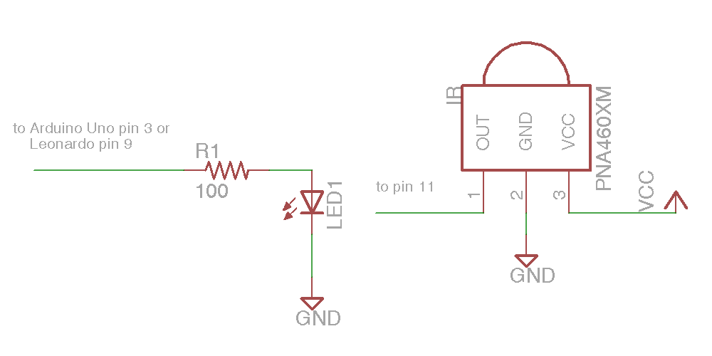
Simple IR I/O Schematic
That was the absolute simplest schematic however the output from the IR LED will be pretty weak because the output pins of Arduino cannot supply much current. You might want to consider adding an NPN transistor to drive the LED.
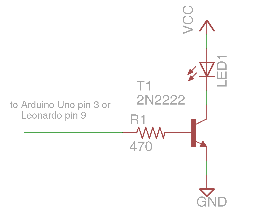
NPN Transistor Driving IR LED
Here is a simple sketch you can use to test if you are receiving IR signals. Is a stripped down version of the example sketch “IRrecvDump” that is in the examples subdirectory of the library.
/* Receiving IR signal and dump the details */

#include

//create a receiver object

IRrecv My_Receiver(11);//Use input pin 11
//create a decoder object
IRdecode My_Decoder;
void setup()
{
Serial.begin(9600);//We will read the output on the serial monitor
My_Receiver.enableIRIn(); // Start the receiver
}
void loop() {
//Loop until we get a signal and pass it to the decoder
if (My_Receiver.GetResults(&My_Decoder)) {
My_Decoder.decode();//decode the signal
My_Decoder.DumpResults();//dump the results on the serial monitor
My_Receiver.resume(); //restart the receiver
}
}
Upload the sketch and start the serial monitor on the Arduino IDE. Point a remote control such as a TV remote at the receiver and press a button. It will dump the information about the signal received. If it’s a protocol with the library understands it will tell you which protocol and it will give you a hex number of up to 32 bits that is the code for that particular function.
To test your transmitter, first determine the 32 bit hex code and protocol that the library can decode. A good example would be the power off/on button of your device assuming that your protocol is supported. As an example I sent a power signal to my Sony DVD player. The dump program tells me that it is a 20 bit code that is Sony protocol and that the value is 0xa8bca. The following sketch is a version of the example “IRsendDemo” in the examples directory of the library.
/*Transmit a power code for Sony DVD*/

#include
IRsend My_Sender;
void setup()
{
Serial.begin(9600);
}
void loop() {
if (Serial.read() != -1) {
//send a code every time a character is
//received from the serial port
//Sony DVD power A8BCA
My_Sender.send(SONY,0xa8bca, 20);
}
}
You will need to substitute the protocol name, the hexadecimal code, and the number of bits for whatever device you are operating. After you upload the sketch type a character into the serial monitor and press enter. Every time you transmit a character from the serial monitor, it will transmit the code you have programmed into the “My_Sender.send(…)” Function call.
In the installments which follow we will explain more of the details of the library including a more advanced circuit for transmitting codes. However for now this should get you up and running.
As promised here are some links to the hardware mentioned in this post
- Arduino Uno available at Adafruit.com or RadioShack.com
- Arduino Leonardo available at Adafruit.com
- 38kHz IR receiver module available at Adafruit.com or RadioShack.com
- IR LED available at Adafruit.com (single unit) or Adafruit.com (25 pack) or RadioShack.com
- 100 ohm resistor at RadioShack.com (5 pack)
- 470 ohm resistor at RadioShack.com (5 pack)
- NPN transistor at Adafruit.com (10 pack) or RadioShack.com
In the next installment will show how to receive and decode IR signals and use them to do something useful such as control a servo.