Imagine yourself being a severely disabled person lying in bed at night and needing assistance. It might be that you’re uncomfortable and need to roll over. Sometimes it’s just something annoying like a bug crawling across your arm. Other times it’s more serious such as a severe coughing spell, nausea, or potentially even a heart attack. A couple of months ago I woke up in the middle of the night with chest pains. I was 99% sure it was just a muscle cramp. I had had my back brace on a little bit crooked that day and I was pretty sure it was just the aftermath of that. But I wasn’t really sure that it was not a heart attack. I tried calling my dad who sleeps in his bedroom which is pretty far from my room. As both of us have gotten older, my lungs are weaker and his hearing is worse. I can usually yell and wake him up in 10 or 15 minutes. However some nights he sleeps very soundly and it’s not unusual for me to lie in bed awake for an hour or even two until he gets into a lighter sleep cycle and can hear me.
As I was lying there in bed wondering if I needed to be calling 911 or if I just needed a rubdown with some BenGay, I wished that I had some sort of a call buzzer that would alert him that I needed something. Years ago I had a call buzzer that we built out of parts from RadioShack. It was part of their home security line of products. There was an emergency call button that you would wire into their control boxes and that control box could in turn be hooked into an auto dialer. We really didn’t need a button to call 911. We just wired in a loud buzzer. We had one for me and one for my grandmother. The radio on the button was strong enough that she could trigger hers in her home next door and it would buzz here.
In 1990 my grandmother passed away and I was using the buzzer myself less and less. We ended up putting it away somewhere because it wasn’t as critical for me and typically if dad didn’t hear me my mom did. In recent years I’ve looked for that gadget all over the house. I’ve looked through closets and junk boxes and junk drawers and cannot find it. RadioShack no longer makes the kind of gadget that we used. Their newer home security systems do not seem to have something similar. I guess they expect you to buy some commercial home security system that is monitored. You know the famous “I’ve fallen and I can’t get up” type of gadget.
So anyway I’m lying there thinking it would be really nice if I had a button in my hand that would trigger a buzzer to wake up my dad. But wait… I did have the button in my hand. I had four of them in fact. Unfortunately all they would do would be to turn on my TV. No buzzers attached.
In previous articles I’ve talked about my “Remote-Controlled Remote-Control” project that I use to control my TV, cable box and DVD players while in my bed.

Sitting in my wheelchair I have no problems pushing buttons on a remote. I use a wooden stick in my mouth.
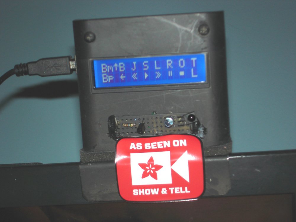
Arduino-based device with LCD menu sits atop my TV probably displaying an Adafruit “As Seen on Show & Tell” sticker.
Original “Remote-Controlled Remote-Control” System
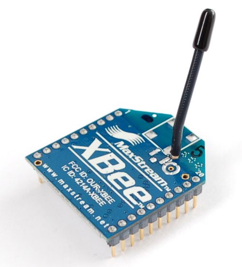
X-Bee Series 1 Radio
My microswitches were wired directly into a traditional universal remote. The box on top of my TV was designed by me and built by my dad and it was based on the Arduino series of microcontrollers. Lots of types of gadgets have been designed for use with these controllers. The most popular RF module is called an X-Bee radio.
I thought about adding an X-Bee to the Arduino on top of my TV, however to trigger it I would need to select that option from the LCD menu. However sometimes I sleep on my side and I could not see the menu. That meant that the X-Bee would have to somehow be connected to the microswitches directly. I concluded that I could build another Arduino gadget to replace the universal remote. The microswitches would wire into the new transmitter Arduino. It would send the IR signals to my set-top Arduino just like the remote did. But it would also have an X-Bee module that was sent RF signals to my dad’s room.
The X-Bee does have some digital input/output pins to which I could connect a buzzer directly. However I wasn’t really sure if it was going to be a buzzer perhaps something that would turn on a light or perhaps trigger an intercom. Since I wasn’t completely familiar with the capabilities of X-Bee and I do know a lot about Arduino I decided that the receiver in my dad’s room would also be an Arduino with an X-Bee connected to it.
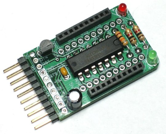
Adafruit X-Bee Adapter
I had no previous experience with X-Bee. It’s a pretty powerful system that allows you to create a network mesh of transmitters and receivers. You can configure them as a master controller which can control either end nodes or routers. The routers can talk to the master controller and to end points. I had several online tutorials and an e-book that many of them talked about the newer X-Bee series 2 devices and I was using the older and slightly less expensive series 1. It was a pretty steep learning curve until I finally found an article that explains how to set up the simplest possible X-Bee network. Here is the link…
http://jeffskinnerbox.wordpress.com/2013/03/20/the-simplest-xbee-network/
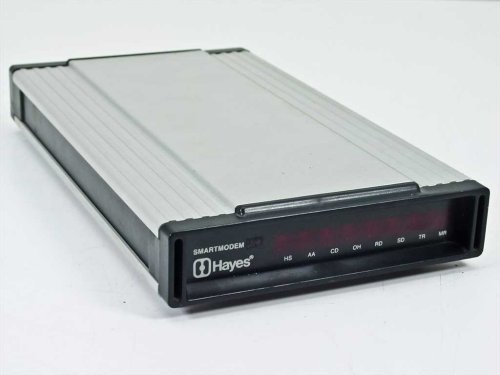 The author explains that X-Bee is really just an ordinary serial modem. In fact the firmware recognizes escape sequences and text commands that are based on an old system used by Hayes Smart Modems. I remember the days when I had an old Hayes Smart Modem 300 sitting on top of my S-100 bus-based computer back in the early 1980s. By the way that “300” wasn’t just a model number… It meant that it communicated at 300 baud. That is approximately 300 bits per second. Today’s Internet traffic is not measured in hundreds of bits per second rather in megabits per second. That shows you how old this system is. Typically an X-Bee radio communicate that 9600 baud.

FTDI USB cable and X-Bee Radio with Adapter
There is a more advanced mode called API mode that allows you to send packets of digital data. But for my purposes all I needed to do was send one character of data that would be interpreted as “Ring the buzzer”.
I first prototyped everything on a breadboard to get it working. Then I had dad solder it all together neatly on a prototype board. Here is a photo of the receiver device that goes in my dad’s room. It consists of an Arduino Micro, an X-Bee radio sitting in the 5 V adapter board, and a buzzer.
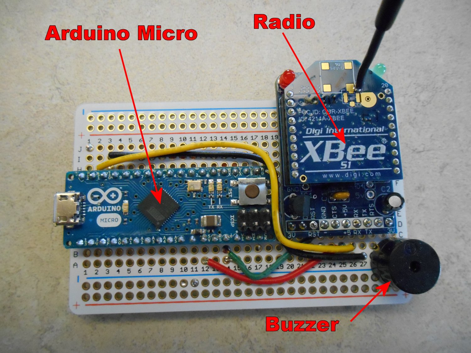
Receiver module with buzzer
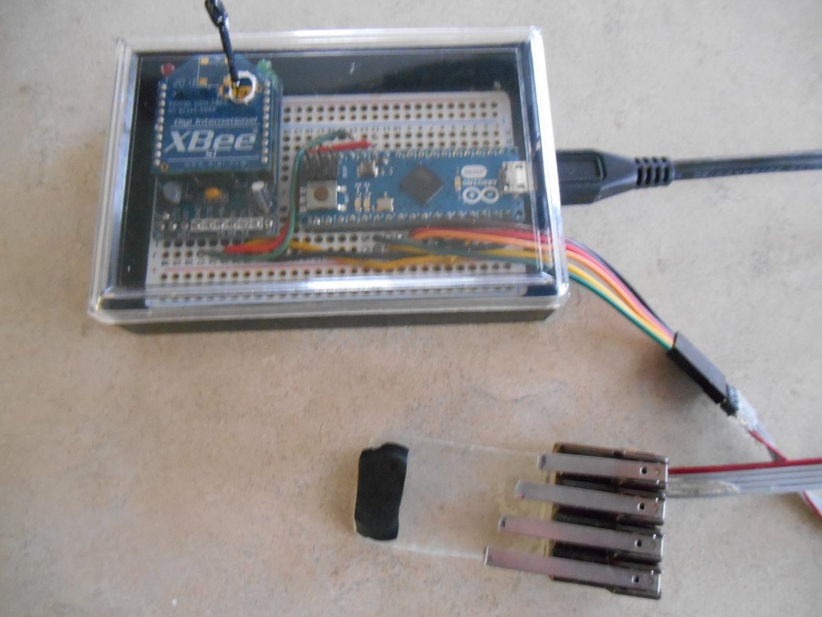
Here is a photo of the transmitter device that sits on top of cable box. It shows the sets of 4 micro switches next to it. The small board on top is an IR transmitter consisting of three transistors and 2 IR LEDs.
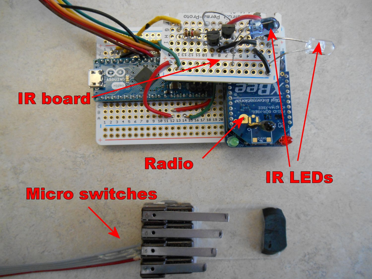
Transmitter with IR emitters and microswitches
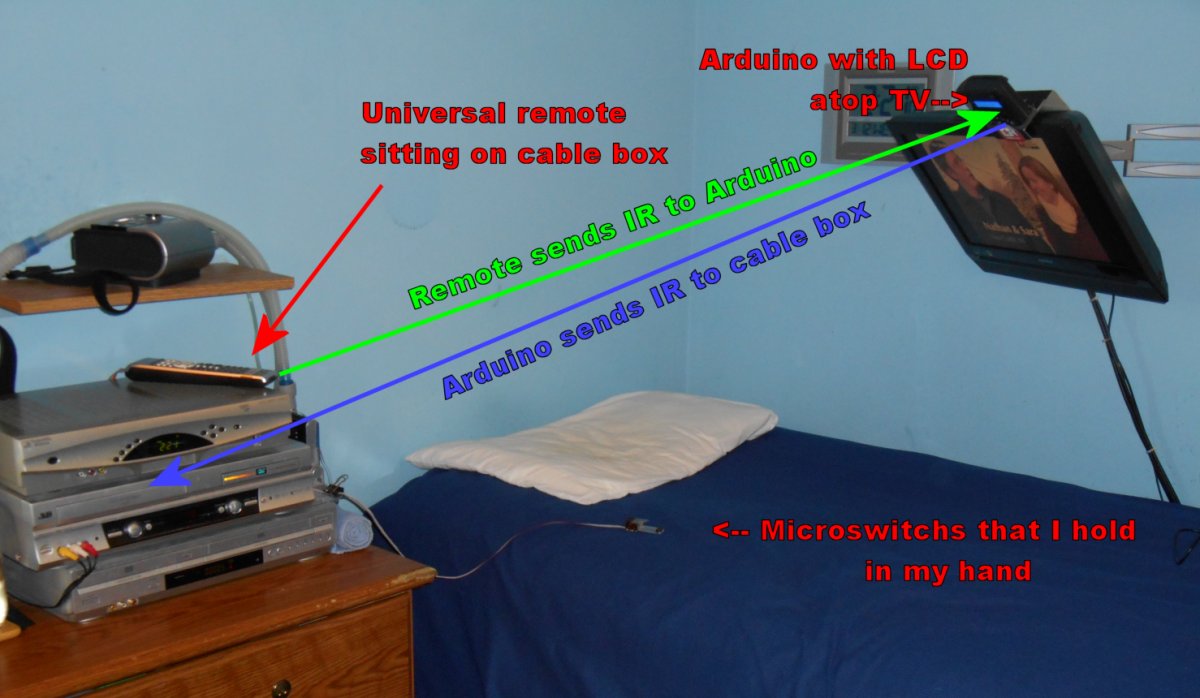
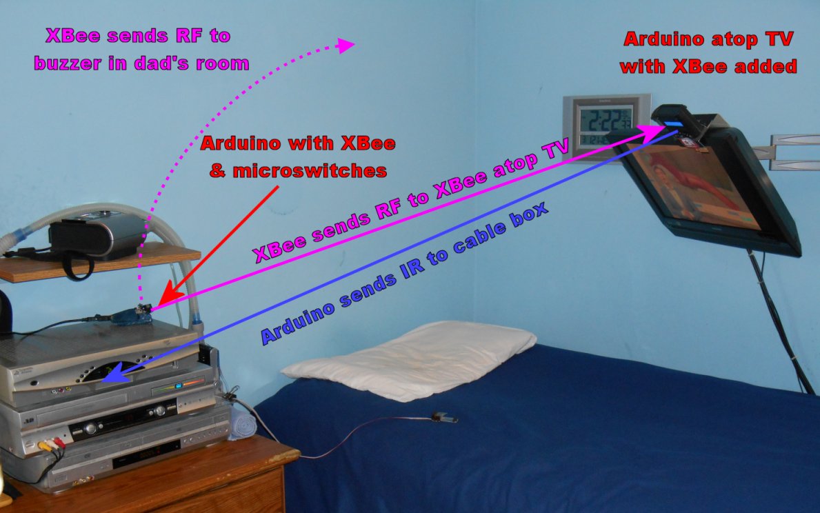
Here is an illustration of how the system worked using the Arduino transmitter with X-Bee radio and IR transmitter in place of the universal remote.
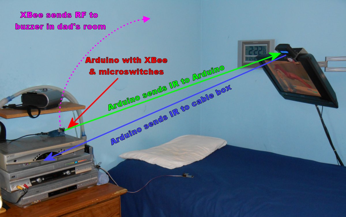
Communication between Arduino devices
I spent several days tinkering with the timing of the system. I had to deal with de-bouncing the micro switches. I also had to deal with conflicts between the IR signals going back and forth between the two boxes. The signal going from the transmitter to the box on top of the TV show by the green arrow would interfere with the signal going from the LCD menu box back to the cable box shown with the blue arrow. The Ghostbusters were right “Don’t cross the streams!”. The original universal remote had been configured to only send a signal once even if you held down the button. I wanted to be able to hold the button to send repeat signals so that it would be easier to scroll through the on-screen channel guide for example. But as the transmitter box with send a second signal, the LCD box would be trying to talk to the cable box and it would get confused.
One of the problems was that the transmitter was too intense. Those double LEDs each with their own driving transistor were putting out too much power. IR receivers have something called an automatic gain control or AGC. They automatically adjust to the amount of infrared light coming in. My ultrabright transmitter was bouncing off of the TV and other objects in the room and temporarily “blinding” the AGC on the IR receiver of the cable box. I ended up putting a piece of tape over one of the LEDs and that helped my timing issues a little bit. While I was able to get it working as well as the old system, I still couldn’t get the timing right to be able to hold the buttons for a continuous stream of pulses for scrolling through on-screen menus.
On the other hand the call buzzer worked pretty well. The first couple of nights that I tried it, my dad was able to hear the buzzer and come and roll me over or do whatever else I needed. I programmed the transmitter Arduino to only trigger the buzzer if I held down 2 buttons simultaneously for a duration of five seconds or more. That way I wouldn’t accidentally set off the buzzer while trying to change channels or do some other function on the TV. Also it meant that I did not need to add any additional buttons.
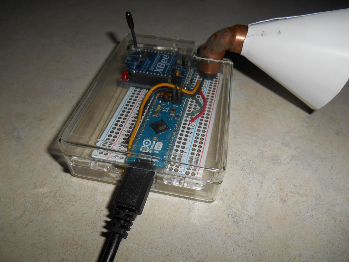
Completed buzzer with cone.
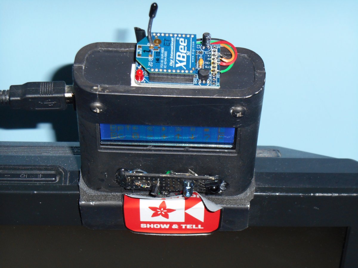
X-Bee mounted atop LCD menu box
We cut away the IR transmitter board from the transmitter Arduino and removed it. We then mounted the device in a plastic box. The boxes we were using were boxes that originally contained a deck of cards. It turns out they are just the right size for the Adafruit half-size prototyping board.
Completed transmitter with IR board removed
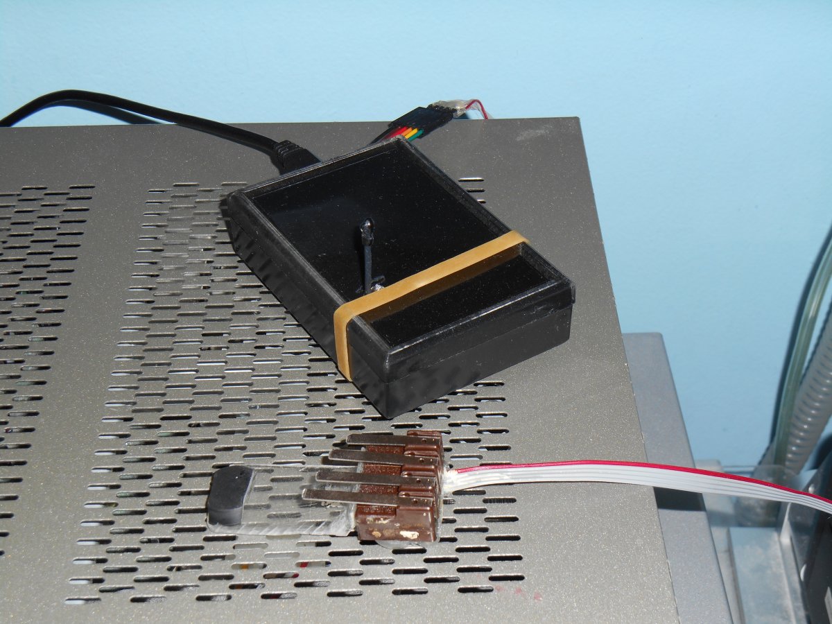
Completed transmitter painted black and sitting atop cable box
Here is an illustration of how the new system works.
Communication between boxes in final version
I mentioned earlier that X-Bee was capable of creating complicated networks with master controllers, routers, and in points. Was a bit worried I was going to have to learn how to do all that once I had added the third radio. As it turns out the simple system of everyone-talks-to-everyone works just as well with more than two radios. Therefore the same RF signal in the same data goes from the transmitter box to my dad’s receiver buzzer and to my LCD box. The data I am sending is just a single text character. If it sends a “^” character then the buzzer goes off. If it sends a “U”, “D”, “L”, “R”, or “S” character than it tells the menu box to move the cursor up, down, left, right, or select. Actually I do not have an up microswitch in the system. It’s easier to get by with just 4 buttons. The menu wraps around and sue if I need to go up, I just go down several steps.
 The whole thing is working really well. I demonstrated my original “remote-controlled remote-control” on the weekly Adafruit Show-and-Tell videoconference on Google+ Hangouts over a year ago when I first created it. Here is a link to that blog entry which contains the video demonstration. A few weeks ago I also demonstrated on the Show-and-Tell the initial X-Bee system that did not include the third radio. Below is the YouTube video of that Show-and-Tell.
Part of the segment begins about 8:30 into the video. I will probably do a follow-up demonstration of three radio system.
Here’s a list of the parts used with links to Adafruit.com
- Arduino Micro with headers
- X-Bee Series 1 module
- Adafruit X-Bee adapter board
- Breadboard friendly 5 V buzzer
- FTDI Friend or FTDI USB cable
- Adafruit half-size prototyping boards
- USB micro cable
- 5 V USB power supply
And in case you’re wondering, I never did figure out if it was a heart attack or not. I tried calling my dad for over an hour that night until I finally got him to wake up. By that time the pain was gone. I’m pretty sure it was just a muscle cramp. Next time I’m prepared!