We are pleased to announce that IRLib 2 has just been updated to provide very preliminary support for Arduino Zero and other SAMD 21 base platforms such as the Adafruit Feather M0 and the Arduino.org M0 Pro.
IRLib 2 is a library for sending, receiving, and decoding infrared signals using Arduino microcontrollers. Until now support has been mostly limited to 8-bit AVR processors such as those used in Arduino Uno, Arduino Leonardo, and Arduino Mega.
The implementation has been tested on all three of those platforms. It provides PWM output at all of our standard frequencies for sending IR signals. It also supports all of our receiving classes including IRfrequency, IRrecv, IRrecvPCI, and IRrecvLoop.
Support is currently limited to using only one specific set of timers and clocks. Output must be on pin D9. As soon as we are able we will make it possible to support other output pins and make use of other timers and clocks so that the system can be as flexible as possible and avoid conflicts with other libraries.
The main users manual has not been updated to reflect these changes. Preliminary details can be found in IRLib2/SAMD21.txt
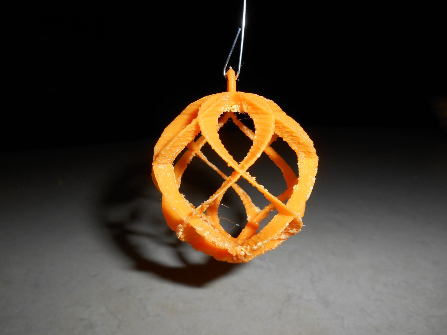
As most of you know I bought a 3-D printer as a 60th birthday present to myself back in July. Mostly I’ve used it to make little boxes for my electronics projects but I thought I would do something a little more fun and print some Christmas ornaments. I did a search on thingiverse.com but the only thing I found it really appealed to me was this one which I printed out. Here is a link to it on thingiverse.com.
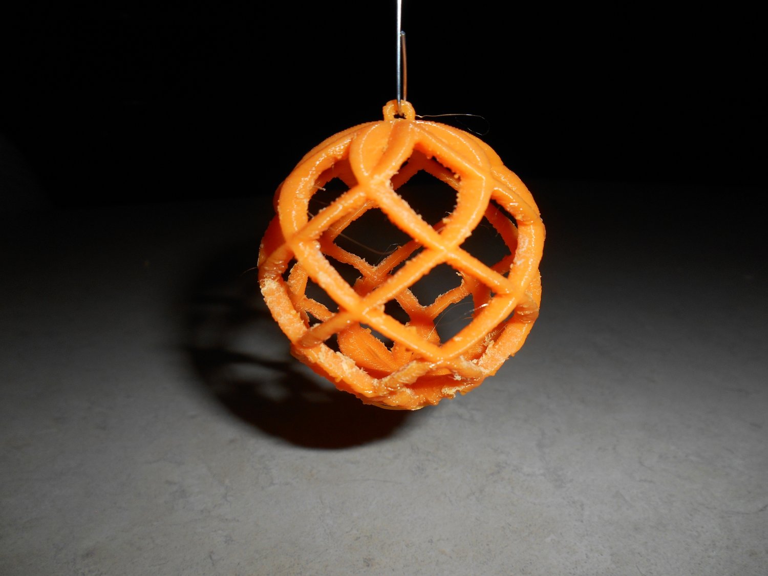
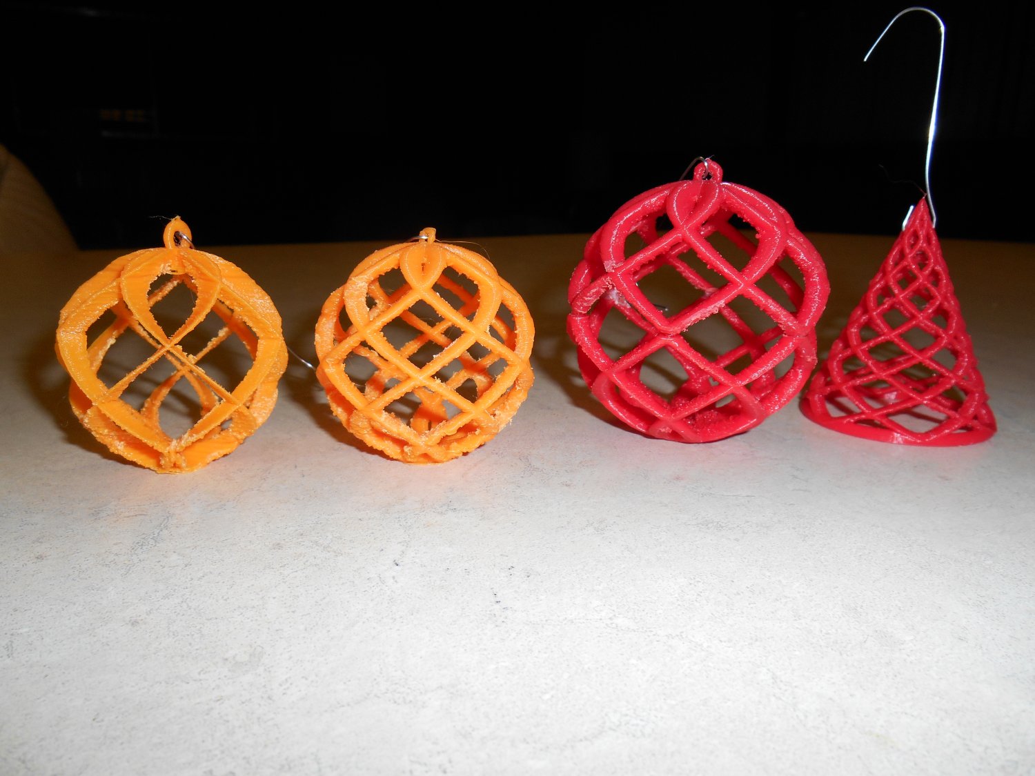
It came out kind of fuzzy but that’s typical for objects that have overhanging parts like this one. I wasn’t really wild about the flat parts of the twisty pieces. I decided I wanted to make one of my own out of rounded parts that were twisted. This is what I came up with.
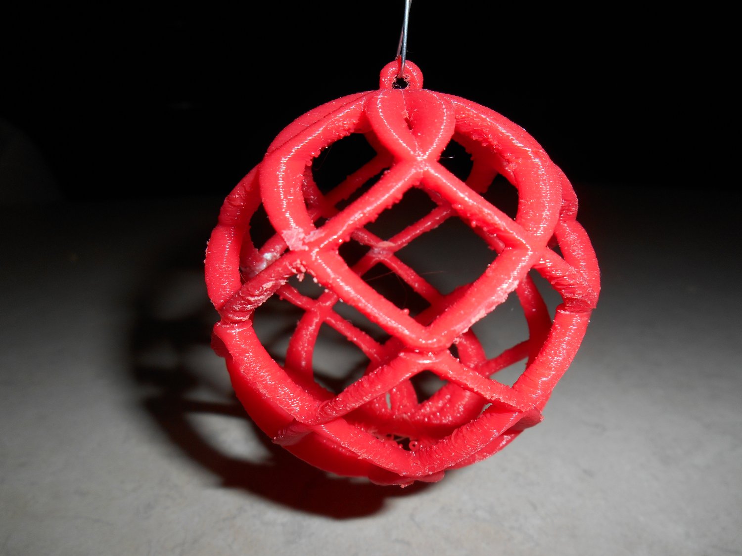
At some point I will post a complete tutorial on how I designed the shapes. This one was sort of a test [that was] 80 percent of the full-size of the model. Again it came out a little fuzzy. When I tried to make one that was larger about three inches tall it kept coming unstuck from the build plate. I also didn’t like the rough edges on the overhanging parts so I cut the model in two, printed the top and bottom halves separately with the curve on the top and the equator on the build plate. Then I glued the two pieces together. Here is a result a little bit cleaner.
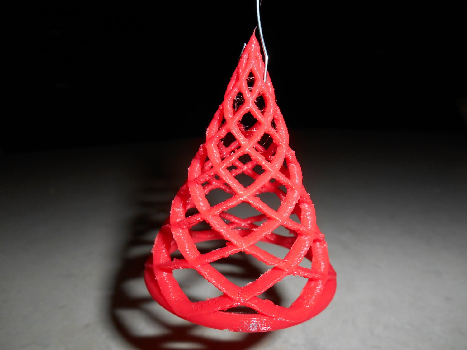
I really liked the twisty design so I decided to make a twisty tree as well. I think I like it even more than the ball.
And here is a link to the Twisty Tree Ornament on thingiverse.
And here is a photo of the entire collection. As I mentioned before at some point I will post a tutorial on how I created them.
You can click on any of the images for larger versions.
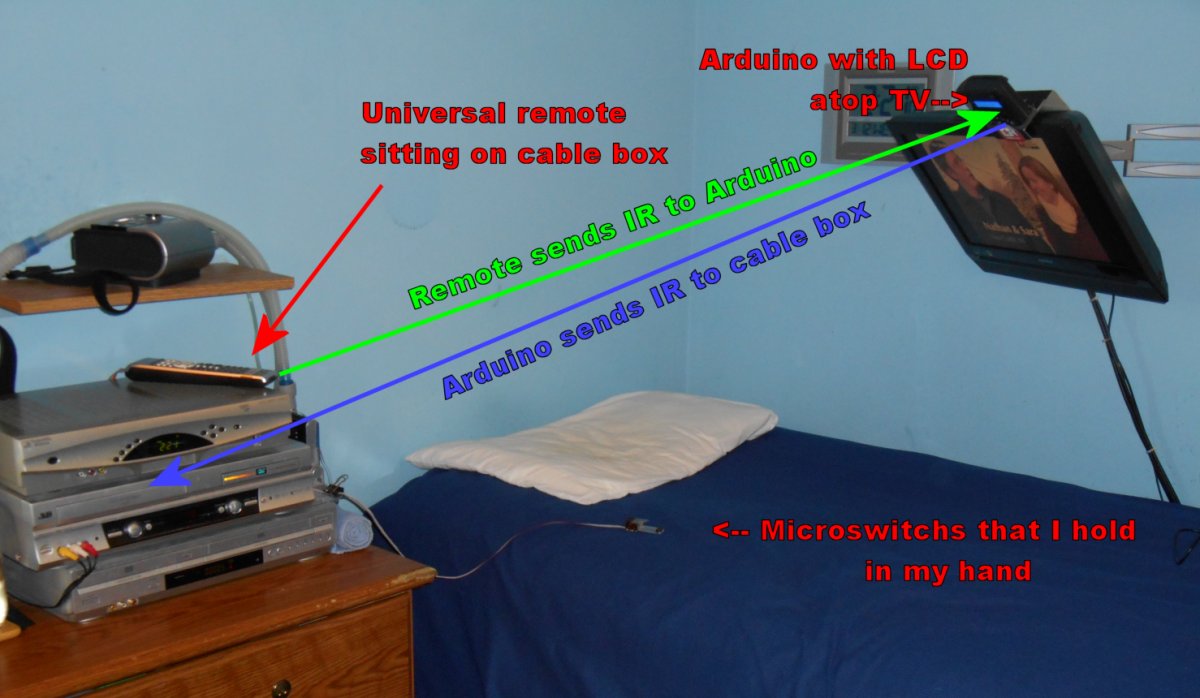
In previous blog posts I’ve described how I am able to operate my TV, DVR/cable box, VCR, DVD player using a custom IR remote with just four buttons. The project has gone through several versions. Originally the buttons were connected to a standard TV remote which would send IR signals to an Arduino box on top of my TV. The Arduino has a small LCD screen with just two lines of 16 characters. By using the buttons like arrow keys I can scroll through symbols on the screen to select dozens of functions. The Arduino box then send IR signals back to the TV, cable box whatever. Here is how the original system looked… (You can click on any image in this blog to see it larger.)
Original “Remote-Controlled Remote-Control” System
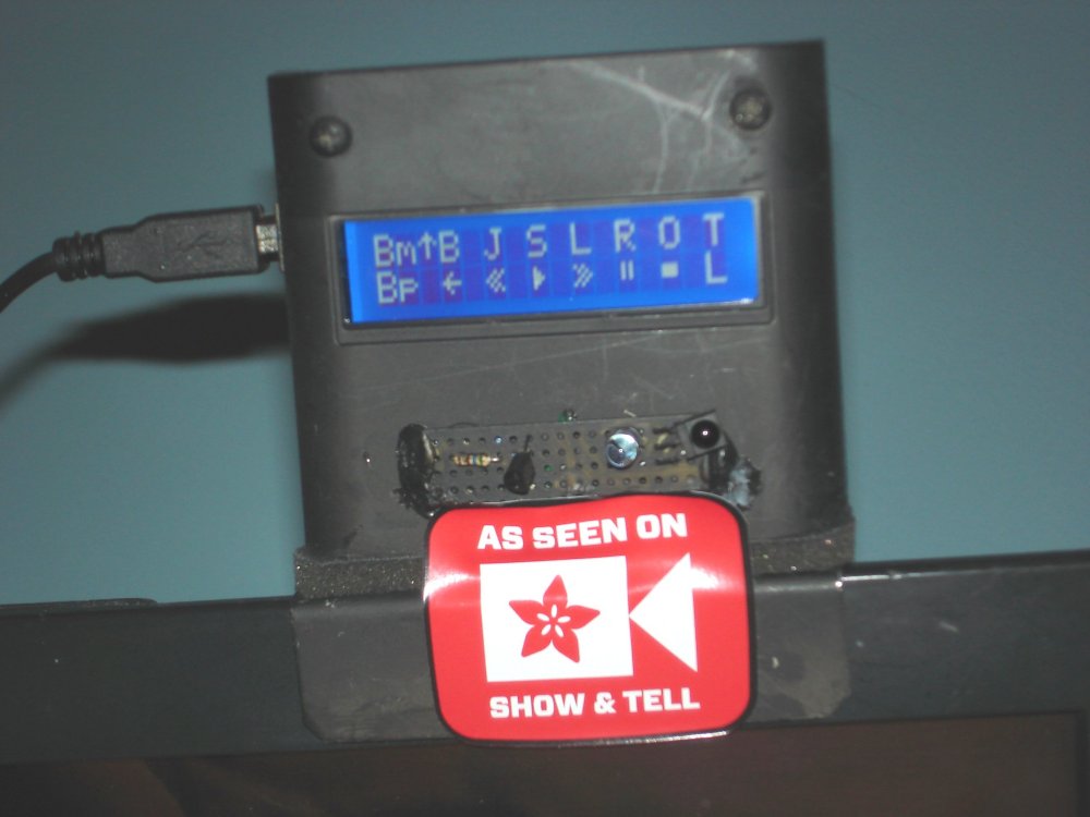
Here is a close-up look at the menu box on top of the TV.
Arduino-based device with LCD menu sits atop my TV probably displaying an Adafruit “As Seen on Show & Tell” sticker.
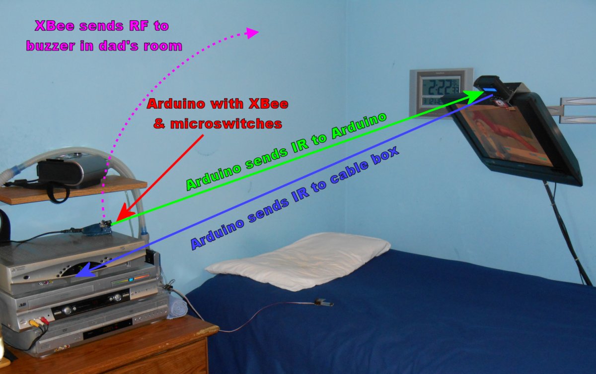
At one point I needed to add a call buzzer to the system that used RF signals that would reach all the way to my dad’s bedroom. Since I was adding an X-Bee radio system I decided I would use RF signals to avoid conflicting IR signals bouncing around the room. The buttons were then connected to an Arduino Micro with an X-Bee radio. It sends RF signals to the Arduino on top of the TV as well as to another Arduino in my dad’s room which has a buzzer in it. If I push single buttons, it scrolls the menus on the Arduino atop the TV. If I push multiple buttons it triggers an alarm that wakes up my dad. Here is how that updated RF system looked…
Unfortunately I seem to be spending more time in bed than I wish I was. My sinuses are mess which causes drainage and coughing spells and congestion in my lungs. The only thing I can do if he gets out of hand is to lie down so that I’m not fighting gravity trying to call things up. Once I’m in bed is such a hassle to give me put back together again that if I have such a spell in the evening I generally just don’t bother to get up again and spend the rest of the evening in bed.
I have a laptop computer that we would occasionally roll in on a bed tray so that I can get online or do other computer things while lying down. But we had to prop the laptop up on a stand so that I could see it. I had to stuff an extra pillow under my head. It was just a big hassle.
I mentioned that I had VCRs in my bedroom. You can see them in the photos above. The stack of devices on the dresser is the DVR on top of 2 VCR/DVD combos. I’m embarrassed to admit that considering how technologically advanced I claim to be. But I was using the VCR every day. I like to watch politics programs on MSNBC. Typically it’s “The Last Word with Lawrence O’Donnell” although I occasionally watch “The Rachel Maddow Show”. I severely miss having Keith Olbermann doing politics. Anyway I record Lawrence O’Donnell every day onto an eight hour tape and when it fills up I have my dad take it to my office where I watch it on a VCR there. (We used to call that “Nike networking”. Copy it to media, put on your Nikes, and walk it over to the other location.) I generally just have it on in the background while I’m doing other things. But how technologically backwards is that? Recording onto a VCR and then physically moving the tape to a different room. I was sorely ashamed. There had to be a better way.
Speaking of technologically backwards… Fortunately Bright House still has about 50 channels that are available as analog cable so it still possible to record them using a VCR. It beats paying extra for their whole house DVR service which comes at quite a premium.
Anyway onto my alternative… I have a small USB device that is in NTSC/ATSC tuner that allows you to connect it to a cable or antenna and watch TV and/or record TV on your computer. It is a Hauppauge WinTV 950q. I thought perhaps I could connect it to a Raspberry Pi and record my programs and then use Wi-Fi to copy them to another Raspberry Pi in my office where I could watch them. Unfortunately without doing a lot of custom coding that I didn’t care to get into, the Raspberry Pi would not support analog recording. I could get it to record over the air ATSC digital broadcast but the Pi either wasn’t powerful enough for didn’t have the right drivers to make analog work. You have to be able to encode MPEG video on the fly. While the Raspberry Pi version 2.0 might be powerful enough, I didn’t really want to mess with it.
I did have in fact a superior alternative. I could use my laptop. You can easily record digital or analog using the USB tuner. What if I just got rid of the VCRs and set the laptop next to my bed. I could run an HDMI cable to my regular TV, put my dictation microphone on my pillow, and have complete access to a powerful PC on my TV screen and it could serve as a custom DVR as well.
The main problem is that the TV I have mounted on my wall only has one HDMI input and I needed 2. One for my cable box for watching TV and the other one for the laptop. Fortunately in my junk drawer I still had a RadioShack HDMI switch. I purchased it in about 2005 when I had my very first HDTV. My first HDTV only had one HDMI input because in those days HDMI was brand-new. I used it to switch back and forth between my cable box and my DVD which wasn’t even Blu-ray. The DVD player in those days had digital up conversion that made standard DVDs look almost HD. The RadioShack switcher would respond to an IR remote. You would simply hold down a learning button while sending it a signal. Then anytime it received that signal again it would switch to the appropriate input. So I would be able to easily switch back and forth between TV and laptop.
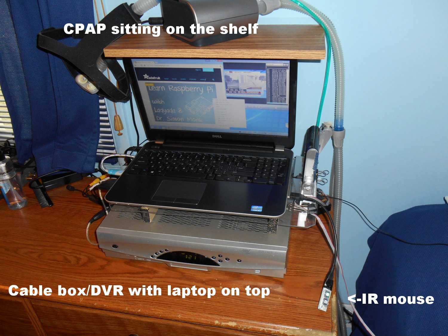
Here’s what it looks like now. Because the cable box has lots of vents on top of it, we had to build a little shelf to raise the laptop up a couple of inches so that the box doesn’t overheat. I set things up on the laptop so that closing the lid does not put it in standby mode. 99% of the time I keep the lid closed and only use it through the HDMI on the TV. The USB TV tuner works just great. And then I had one other brainstorm…
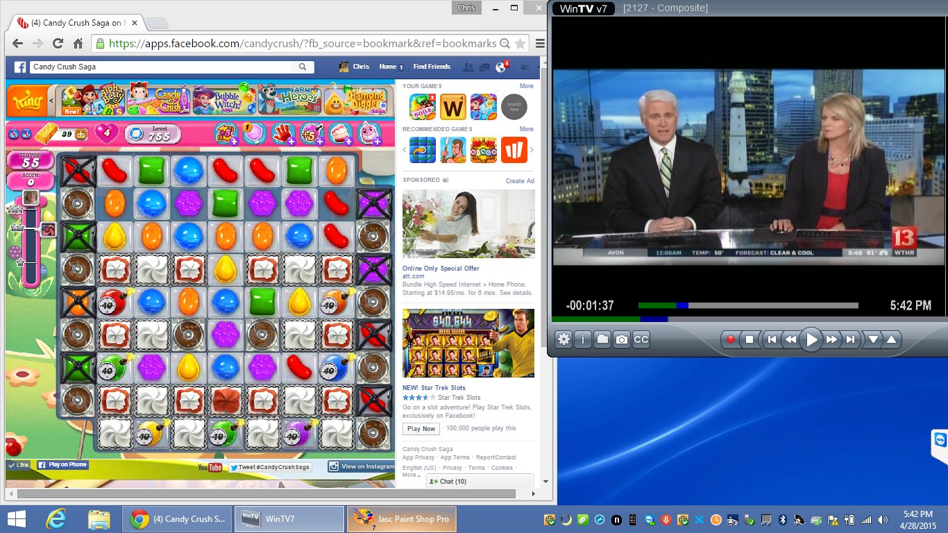
In addition to a coaxial connection to which you can attach cable or antenna, the USB tuner also has a place to plug in an adapter with Red, White, Yellow RCA composite cables. By connecting them to the cable box I can then copy things from the cable box onto the TV tuner/laptop. That’s one of the nice things about the old VCR was that if I did record something on the cable box that I wanted to keep long-term, I could always make a low definition VCR recording of it for posterity. This would preserve that capability and add one other capability. There is a program that allows you to watch TV on your PC through the USB tuner. So if I’m using the laptop, I could put the TV program off in the corner of the screen and watch my cable box low definition through the component cables. Then on the rest of the screen I can log into Facebook, play games, write blogs whatever. It essentially made my laptop screen a-picture-in-picture capable TV with the TV in the small window and the laptop screen in the remaining area. Here is what it looks like on my laptop where I can watch TV and do other things at the same time.
Screen grab from my laptop shows me watching the news through the USB tuner while playing candy crush.
Here is an overview of how everything communicates together.
IR and RF communication between my various devices.
I thought everything was going to work just great. All of the initial tests worked perfectly. But then I started having audio glitches. For some time, I had been having problems with audio not working between the TV and the cable box. You had to turn on the TV first and then turn on the cable box in order for the HDMI to sync up properly. However when I added the HDMI switch, for some reason it wouldn’t work properly. It probably had something to do with the HDMI switch being on all the time. Whenever it would glitch using direct connection, I could usually power things off and on and get them to re-sync but because I couldn’t completely powerdown the HDMI switch, I could not get it to work properly.
I didn’t really like using the HDMI switch and the TV was getting kind of old. So I just went over to Best Buy and picked up a new Samsung for the bedroom that had 2 HDMI inputs. Until then I had to watch TV using the USB tuner through the laptop. That was the only way I could get audio. But of course I also had to get another very long HDMI cable. While we were installing the second cable, my dad noticed that the original cable had gotten pinched beneath the bed wheels and had been damaged. That may have been the source of the audio problems to begin with. So it took another couple of days to get yet another cable which meant another couple of days of only watching low definition TV through the laptop.
Just as I got everything hooked up properly with the new TV, no HDMI switcher box, 2 brand-new cables, I hooked it all up and the HDMI on the cable box quit working altogether. I tried using different cables. Tried the old TV. Tried with or without the HDMI switch. Basically the cable box was fried. I could still get analog audio and video through the USB TV tuner and the laptop but HDMI audio was fried. I probably damaged the box by using the damaged cable. Something probably shorted out and ruined the cable box.
Unfortunately my DVR/cable box is in a permanent state of near overflow. Have you ever heard of the phrase “floating checks”? That’s where you write a check from one bank account to cover an overdraft in a different bank account and then you write a check from that bank account to cover the overdraft in the first one. Well, I practice a similar procedure “floating recordings”. When I run out of space on my DVR, I look at the movies I have recently recorded and look for another airing of that same movie a few days down the road. I then erase the movie, schedule it for re-recording as far in the future as I can, and then use the free space to record something today. I keep doing that over and over until the movie isn’t being shown anymore. Then I have no choice but to watch it or give up and delete it permanently. The bottom line is my DVR is always very, very full.
I know of no cable company that allows you to transfer recorded programs from one DVR to another. So when your box goes bad, you are screwed. I could still watch the programs in low definition. I could even copy them to tape on the VCR. But it would take me forever to catch up and in the meantime if I was ever going to get anywhere, I had to stop recording new programs.
I finally came up with a brainstorm. We would get a new replacement cable box and I would move the broken one to my office where I could either watch programs and/or copy them to the VCR in my office. New programs would be recorded on the new box so that the old one wouldn’t get any fuller. Eventually I would get caught up and turn in the box.
We already have two DVR’s. One of them in the living room and the one in my bedroom. The one in living room is a newer model that has more capacity but it still seems to fill up with ease. Both of the DVR’s are limited to 2 programs at once each. So you can record two programs simultaneously in the living room, two in the bedroom. But that’s it. You can watch recorded programs while recording 2 programs or you can record one and watch one. Even though we have a total of four streams between the two, it’s only two in the living room and two in the bedroom. Recording conflicts are a constant hassle both places.
Fortunately Bright House is now offering a premium DVR. It has 1 TB hard drive which is double the capacity of their previous big DVR and probably quadruple the capacity of the one I had in my bedroom. But the really great feature is allows you 6 streams of HD simultaneously. That means you can record five things at once and watch a sixth. After talking it over with dad, we agreed that a few more dollars a month for this DVR would be well worth the price. He went to Bright House headquarters and picks up a new enhanced DVR. We put it in the living room. We moved the living room DVR to my bedroom. And we moved my bedroom DVR to my office where I would watch down its content and/or record it to tape.
Before moving the damaged DVR to my office, I tried disconnecting the coaxial input cable to see if I could still watch recorded programs with the cable disconnected. I was able to do so successfully. So we moved everything to the office, connected it to the office TV and VCR and tried to turn it on. It wouldn’t work. It would not load the software without being connected to the cable. When I disconnected it and tested it in the office, I did not unplug the power so it didn’t lose its software. It would indeed work without being connected to cable but not after the power had been turned off and on. The problem is I don’t have cable in the office. The only other place I could get to it easily is in the kitchen at our bar between the kitchen and the family room.
So we disconnected everything, dug out one of my old VCRs that I had just put away, and reconnected everything in the kitchen. I then spent the next several days watching some programs while eating lunch at the bar in the kitchen and copying other programs to tape. It only took me about three or four days and 4 eight hour VHS tapes. Some movies I was able to “float” by erasing them from the old broken DVR and re-recording them on the new one as they were scheduled over the next several days.
Finally everything is working perfectly. I can use my laptop and watch TV easily in bed. We adore the new six stream DVR in the living room. You never have to worry about recording conflicts. Only one time in the past two or three weeks have we even come close to having five simultaneous recordings and we could have easily avoided that if we had dried. But the point is we didn’t have to juggle things. Five was enough. The large capacity drive is great as well although my theory is it doesn’t matter how big your hard drive is, eventually you’ll find a way to fill it up. Were only about 30% on this one and we have a ton of stuff recorded already. I don’t think we’re going to run out. If we do, shame on us.
One final modification to the whole system involved the mouse on the laptop. As I mentioned in other blogs, the voice control software I use Dragon NaturallySpeaking doesn’t work very well with the mouse. On my desktop computer I supplement the voice control by using an IR remote control mouse that I built using Arduino and sometimes a mouse control app on my android phone (formerly on my iPod touch).
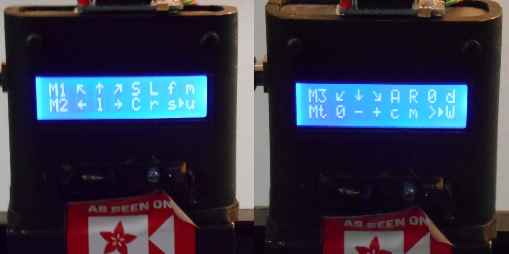
While using the laptop in bed on the bed tray before we set up this system, the voice control program would occasionally hang up or I would have trouble using the mouse. On my desktop machine, if the voice control hangs up, I can get it going again using the mouse alternatives. But in bed I did not have those alternatives. Although wait a minute… I do have an IR remote. The Arduino box atop my TV is an IR remote. All I had to do was reprogram it to use the codes for my IR mouse device. I also took the opportunity to remove all of the software I had put in it for controlling the VCRs and DVD players that I no longer needed. You are a couple of images of the menu screen that shows the new mouse commands.
The screen can only show 2 lines of text at once. You can scroll it up and down. The image on the left shows the first two lines of the mouse control section. The “M1” and “M2” at the start of the lines just tell me it’s the first and second line of the mouse control section. The arrows next to them move the mouse up, left, right, or diagonally. The “l” in the center means “left click”. If you look at the image on the right, you can see the sections for moving the mouse down and diagonally. Just to the right of all of the arrow commands you will see a capital “S”, “C”, and “A” which correspond to Shift, Control, and Alt. The “L” means “hold the down the left mouse button” and the “R” means hold down the right mouse button. Also “r” lowercase means simply click the right mouse button. The “f” and “s” make the mouse move faster or slower. The “u” and “d” options move the scroll wheel up and down. The “W” presses the Windows key. The “m” on row “M1” changes mode from mouse mode to keyboard mode. That makes all of the arrow selections control the arrow keys on a keyboard rather than mouse movement. The row labeled “Mt” is mostly TV commands. The “0”, “-“, and “+” control mute, volume down, and volume up. The “c” and “m” switch the HDMI switch to either “cable box” or “monitor for laptop”. The “>” symbol performs a Win+right arrow. Which will dock your currently open window to the edge of the screen. A command I use quite often.
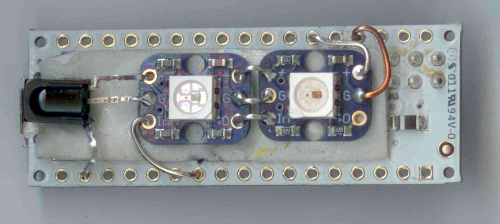
Arduino Micro configured as IR mouse as used on this laptop and in my tutorial for Adafruit.
Although on my desktop PC I use this larger Arduino with a 20×4 character LCD screen, on my laptop I use this tiny Arduino Micro with just a couple of neopixels as indicators to tell me if I’m dragging the mouse or holding down the shift key or other functions. Unfortunately I can’t see those indicator lights the way I have things set up so I’m going to have to come up with an alternative to that. But I really have some ideas.
Prior to this new set up, the only time I ever used laptop in bed was if I had to lie down early from a coughing spell. However now that it was easy to get to, I’ve been using it more and more. When I initially lay down I have no trouble using the dictation software. I usually go to bed about 9:30 or 10 PM and watch TV. Then at about 11 PM I change into my pajamas and put on my CPAP respirator. It’s a mask that covers my nose and puts air pressure into my lungs to keep them inflated and prevent apnea. I typically watch more TV from 11 PM till about 12:30 AM or 1 AM with the CPAP on. However I had never used the laptop and the dictation software with the CPAP on before. It turns out that with the machine blowing air up your nose, one does not talk as plainly as one normally does. The dictation software doesn’t understand me nearly as well with the respirator on. Words such as “nine” come out as “dine” and “mike” comes out as “bike”. You can’t stop the air from rushing out of your mouth when you have the CPAP on and try to talk. So all of the soft sounds come out hard. That means being able to use the IR mouse is much more important when I have the CPAP on than normally.
Windows has a built in accessibility feature that pops up a keyboard window so that you can click on it with your mouse as if you were typing on a real keyboard. Most of the time I don’t need it. Late at night I’m either just browsing Facebook or crushing some candy. I don’t really need to do typing and the dictation software does work somewhat if needed.
Overall it’s been a real blessing to be able to continue to do productive work while in bed especially on those very frustrating days when I have to spend more time in bed then I want to spend there.
Among the things I’ve worked on in bed is writing a tutorial for the Adafruit Learning System on how to create an IR controlled mouse using an Arduino Micro. That is the same device I’m using on the laptop for mouse control. Adafruit is where I purchase all of my electronic parts. They describe themselves as not being a store for selling electronics. Rather they are a tutorial website with a really big gift shop. When I showed off the project at a recent Adafruit Show-and-Tell video chat on Google+ they thought it was most interesting that I actually used the IR mouse to write a tutorial on how to create an IR mouse. Here is the video from that presentation.
Had a scary moment yesterday when I thought someone had hacked my computer.
I’m sitting here at the PC searching some website or doing Facebook or I forget what I was doing. Suddenly my mouse started going crazy. Begin jumping all over the screen wildly and I couldn’t control it.
I don’t ever really use an actual “mouse”. There is one connected to my computer in case somebody else needs to use it but I never touch the thing because of my disability. I actually have three different ways of controlling a virtual mouse. Most of what I do on my computer is dictate using voice recognition software called Dragon NaturallySpeaking. It has a variety of mouse commands such as “Move Mouse Up” or any other direction. You can also “Mouse Click” or “Mouse Double Click” or “Right Click” by simply saying those words with a pause before and after so that it knows that you’re not actually dictating. It also has commands for dragging the mouse which I bit difficult to use and you can move the mouse using a grid system that I won’t bother to describe here.
Additionally I have an Arduino Leonardo microcontroller configured as a USB mouse and keyboard emulator. It has IR receiver that lets me use my TV universal remote to send infrared signals and control the mouse that way. Details can be found here.
Also I have a special driver loaded on my PC the connects to an app on my android phone (my iPod touch prior to that). I can use my stick in my mouth to drag around on the app and click on buttons to control the mouse.
I desperately tried to shut down all the programs I was running to do a reboot but it was difficult to do with the mouse jumping all over the place. I couldn’t click on anything because the mouse was never in the position I wanted it to be in. None of my three methods of mouse control could override this erratic behavior.
Just as I was ready to close my last window, I happened to look over at my actual mouse lying on the desk. Except it wasn’t lying on the desk. It was lying on top of a bunch of junk piled on my desk. Most of them were cables clumped together in a tangled mess. Sunlight was pouring through my office window and reflecting off of the desktop, the cables, and other shiny objects lying in the pile. I finally figured out what the problem was.
I got hatcked by the sun!
Although the original design for the computer mouse had a little rubber ball in the bottom of it that had to actually touch the surface of a table, all modern mice are optical mice. The original optical mice simply had an LED and a photosensor and could only be used on specially designed mousepads that had a herringbone pattern on them. But the latest optical mice actually have a tiny camera that focuses on the surface of whatever you are dragging it across. It can detect the movement of microscopic textures as the mouse moves and from that determine the direction in which you are moving the mouse. In this case the mouse wasn’t moving but the sunlight bouncing off of the table and other junk beneath the mouse was flickering and tricking it into thinking that it was being dragged across some surface. As I was attempting to close the last window and reboot, the sun went behind a cloud and the mouse stopped moving.
I had my dad come in the office end mouse firmly on the table. There’s been no further incidents of “hacking”.
So not only did I get hacked by the sun… The hacking was stopped by a cloud 🙂
I’ve been working with the new Pinoccio microcontroller Arduino-like platform for creating internet-of-things devices. One of the many ways you can access devices through a webpage called their headquarters. It is available at hq.pinocc.io and requires a special plug-in for Google Chrome. I had been having great success with the device and suddenly two days ago the webpage quick loading. At first I thought their server was down but eventually realized that I could login using other in my home but not the one that I had been using. It was the classic “why is this thing not like the others?” problem.
The folks at pinocc.Io were tied up in a maker fair and working on other issues and were not able to help me right away. So I did some exploring on my own.
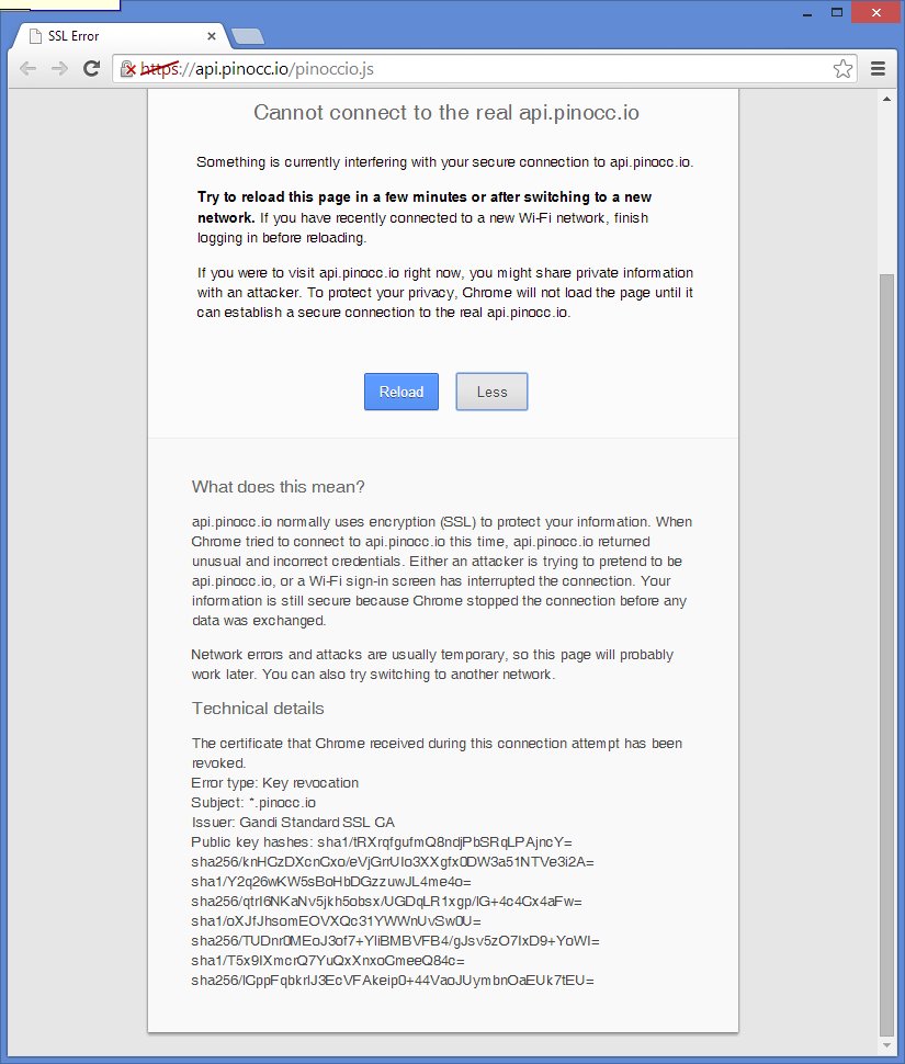
I finally figured out that it was a problem with SSL certificates on a piece of JavaScript. I only figured that out by typing in the URL the JavaScript itself instead of the URL of the webpage. That gave me the following…
Note you can click on any of these images for larger versions.
I clicked on the “MORE” and got the following information.
That told me that the certificate had been revoked and it told me who had issued the certificate but that still tell me very much. The first problem was figuring out where in Google Chrome SSL certificates were handled. Several Google searches later I determined that chrome uses Windows computers default settings. You can get to it in Google Chrome’s settings under the section “proxy settings”. (Gee no wonder it didn’t jump right out at me!) You can also access SSL certificate information from Internet Explorer under Tools… Internet options… content tab. I tried clicking on the “clear SSL state” hoping that it would flush everything out and recheck the certificates. That didn’t help. I clicked on the “Certificates” button but couldn’t find anything related to the certificate issuer “Gandhi Standard SSL, CA” that I had gotten from that more detailed error message.
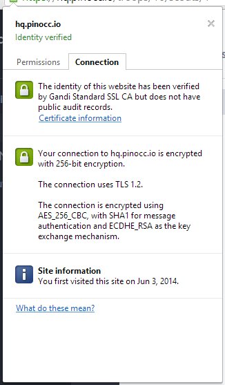
I browsed around the certificate section in Internet Options but could not find anything under any of the tabs regarding that provider. Then I noticed that where you type the URL there is a little green padlock icon that somehow was beckoning me to do a right-click on it.
When I did I got the following…
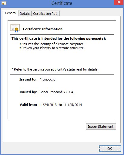
The initial tab talks about permissions but I clicked on the Connection tab. Then I clicked on the Certificate Information link. Which gave me this…
The details tab was interesting but didn’t really tell me much so I tried the “Certification Path” tab and got the following
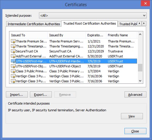
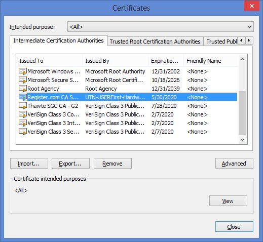
This gave me some other places to look. I started the top with USERTrust and found it under “Trusted Route Certification Authorities” here…
However it would not allow me to remove it. However under “Intermediate Certification Authorities” I found an entry that it would allow me to remove.
After clicking on the “Remove” button and closing everything out, I was able to go back into Google Chrome, access the website, and it loaded perfectly. It apparently went and got a fresh copy of the certificate. Now everything is working fine.
The folks at Pinocc.io later explained “We recently added a load balancer which was still configured with the pre
heartbleed ssl cert we revoked. This has been fixed.”
So if anyone is out there reading this whether they are using Pinocc.io or not and you are having SSL Certification problems perhaps the steps I’ve shown you will help.
IRLib Version 1.4 is now available on GitHub at https://github.com/cyborg5/IRLib/. It includes minor upgrades to the debugging macros, a new system for decoding based on absolute tolerance in microseconds rather than a percentage tolerance. Also included is a new example sketch which implements the Phillips RCMM Protocol. The 32-bit version of that protocol is used by AT&T U-Verse cable boxes. Note that there are some unusual timing requirements in this protocol. The decoding routine works best when used with the IRrecvLoop or IRrecvPCI receivers. The sending of IR codes however should work well.
Details about these changes in the unusual decoding requirements of this protocol will be included in an upcoming documentation on how to implement new protocols for this library. That documentation should be available in a few weeks.
We are announcing the creation of a new users manual for IRLib. A library for Arduino for sending, receiving, and decoding infrared signals.
This is a work in progress. It will eventually contain three sections.
Reference
Tutorials and Examples
Implementing New Protocols
Currently only the reference section has been completed. The tutorial section currently only links to previous blog posts that contain tutorials. That section will be expanded. The third section on new protocols will be written soon.
A Microsoft Word and Adobe PDF version of the document is also available in a new folder added to the GitHub repository for the code. That repository is available at.
Down three IRLib is a library of code for Arduino-based microcontrollers that facilitates sending, receiving, decoding and analyzing infrared remote signals. Here is an overview of the changes.
NEW FILES
Added new file IRLibRData.h and moved irparams structure and related items to that file. Allows users to create custom IRrecv classes
NEW EXAMPLES
Rewrote Samsung36 example to include both send and receive
Added new examples for new protocols DirecTV and GIcable
Added new example IRanalyze gives more detailed analysis of timing. Useful in analyzing the protocols
Added new example IRfreq reports modulation frequency of a signal. Requires TSMP58000 IR learner chip
Cleanup of other example routines.
NEW CLASSES
Created IRrecvBase class to allow custom receiver classes. IRrecv is now a derived class from it.
Created IRrecvLoop class which receives IR signals without using any hardware interrupts or timers. Also created IRrecvPCI class which uses Pin Change Interrupts to receive IR signals. These new receivers are more accurate than the 50µs timing of the original IRrecv. However they also have other limitations described in comments.
NEW FUNCTIONS, VARIABLES AND METHODS
In IRrecvBase added “unsigned char Mark_Excess” with default value 100. Was a define macro but now is user settable.
In IRrecvBase added method “unsigned char getPinNum(void);” which retrieves the pin number used from irparams.recvpin. This value not normally accessible to end user.
Globally available function “void do_Blink(void);” blinks pin 13 LED. For use by user created extensions of IRrecvBase.
INTERNAL CHANGES
Data collected by IRrecvBase classes in irparams.rawbuf is now converted to actual microseconds rather than clock ticks of 50 µs each. IRrecvBase::GetResults has a new parameter “Time_per_Ticks” that is used to convert ticks into actual microseconds if needed.
Adjustments to mark and space to deal with overreporting and underreporting of intervals is now done once in IRrecvBase::GetResults eliminating the need for MATCH_MARK(d,v) and MATCH_SPACE(d,v). Just use MATCH(d,v) everywhere.
Modified IRLibsendBase::mark() and IRLibsendBase::space() to overcome limitations of “delayMicroseconds()”.
Changed many int to char or unsigned char to save memory
Eliminated DEBUG macro in IRLib.h and its use elsewhere. Macro TRACE is more useful.
Changed IRTYPES to unsigned char and a list of #defines rather than an enum (even though I still really like enums, changing it saves memory)
MEMORY EFFICIENCY
Code changes result in memory savings of approximately 54 bytes in code space and 39 bytes of RAM.
I have a little Christmas tree that I put up in my office every year that I call my “Charlie Brown tree”. It’s a scrawny looking little artificial tree with a little white Christmas balls on it and a strand of cheap flights. This year I decided to fancy it up a little bit by adding a 3 meter strand of Adafruit neopixels containing 90 pixels. I started out with the standard strand test sketch that is available from Adafruit and then modified it to add my own special patterns. I showed it on a recent Adafruit Saturday night Show-and-Tell Google+ video chat. There were a number of other Christmas displays shown that night but people seem to especially like my candy stripe pattern.
One viewer liked it so much he wrote me and asked me for the candy stripe code. He then incorporated it into his outdoor display and showed it in a subsequent Show-and-Tell a few weeks later. I had always intended to write a blog post about it and to include the code but I got so busy over the holidays that I didn’t have time to clean up the code and make it suitable for public sharing. The holidays are over and I’m finally getting around to sharing the code.
Here is a YouTube video showing a slightly earlier version of the pattern.
Here is the Adafruit Show-and-Tell on Google+ where I showed off the tree and my blinking Christmas card.
Here is the Show-and-Tell of the other guy named Kenneth who borrowed my candy stripe code. His display used a full 10 meters of pixels. Unfortunately there were bad audio problems that evening but I will put the video here anyway. His segment starts at about six minutes into the video.
Here are some links to the products used in this project. All were purchased from Adafruit.com
Our friends at AnalysIR who make Windows software to assist in decoding IR signals have come up with a nice schematic for a constant current IR LED driver circuit that we thought would be of interest to our users here. Here is a link to their blog post describing the circuit. We’ve not tested it out here yet but we have seen similar schematics and we trust these guys to do it right anyway. Their explanation of the circuit is outstanding.
AnalysIR blog post on constant current IR LED driver
They also have many other interesting articles in their blog and they have a user forum with lots of interesting information and exchange of ideas between users.