Click this logo to see my Adafruit Show-and-Tell presentation June 22, 2013
The reason I got into working with Arduino and IR remotes was to create adaptive technology for disabled people like myself. After building a specialized TV remote, the next project I tackled was to create an IR remote controlled mouse and keyboard emulator that allows me to use my IR remote to move the mouse, the arrow keys, and even type complete messages using a full keyboard.
First I would like to share with you some background as to why I created this device and then we will show you how to make a simplified version of this IR remote mouse that would be useful to anyone who uses a computer… not just someone with a disability.
My Dragon Isn’t Draggin’ Very Well
Normally I control my computer using dictation software known as Dragon NaturallySpeaking however there are some things which Dragon does not do well. Ironically a program called “Dragon” isn’t very good at draggin’ the mouse. There are mouse control commands but they are sometimes difficult to use. Also it is very difficult to use control click, shift click and (although I’ve never had to) alt click. I also have a graphics program which occasionally requires you to drag the mouse holding the right button. To my knowledge there’s no way to do that with Dragon. I also have an app on my iPod touch which allows me to wirelessly control the mouse. However it has even fewer dragging capabilities than Dragon. And there are just times when Dragon gets locked up for some reason and doesn’t work. I needed an alternative way to access my computer when something goes wrong with my usual methods. So creating an Arduino-based IR controlled mouse has been a real godsend.
Okay you’re thinking “Come on Chris isn’t it a little bit egotistical to call a device you designed a godsend?” But it really has been a blessing that such technology is available for me to create this device. When I first came up with the idea for it I was going to have to use a Arduino Uno. But it isn’t very well suited to doing mouse and keyboard emulation. You have to use an ISP to reprogram the USB controller and then you have to use an ISP to upload sketches. I had done Google searches to learn how to do it and it wasn’t going to be fun. There were some libraries available but I thought it was going to be a pretty steep learning curve about USB protocols in order to write the code to make this happen. I was still very new working with Arduino and I wasn’t looking forward to getting into something that complicated.
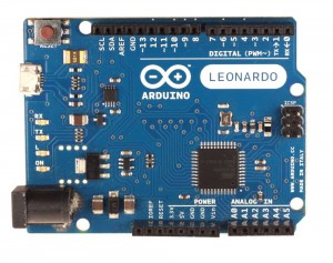
Arduino Leonardo
Leonardo to the Rescue
Finally one day I did one last Google search on “how to emulate a mouse using an Arduino” and up popped something new! A new kind of Arduino called “Arduino Leonardo“. It was designed specifically for this purpose to be able to do mouse and keyboard commands. It has all of the necessary libraries built in. I could use the device as a mouse or keyboard and I could still upload sketches directly through the USB port using the traditional Arduino IDE. It literally brought tears to my eyes when I realized that what I feared was going to be unbelievably difficult was now going to be almost trivially easy. I immediately went to the Adafruit website and ordered a brand-new Arduino Leonardo and other necessary parts to build the device shown below. Inside the box is a Leonardo, and IR receiver, and a 20 character by 4 line LCD text display and then I2C backpack for controlling the display. Here is an image of what I built and use every day.
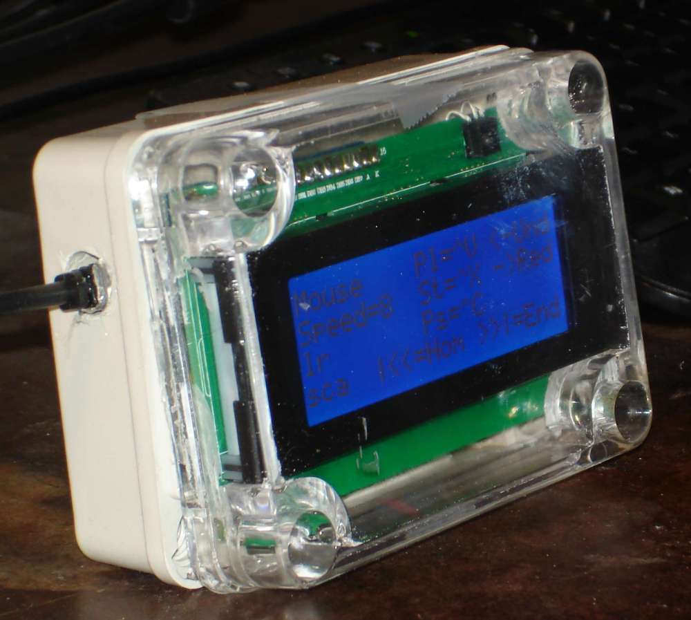
My Leonardo-based Mouse and Keyboard Emulator
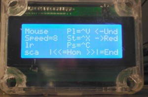
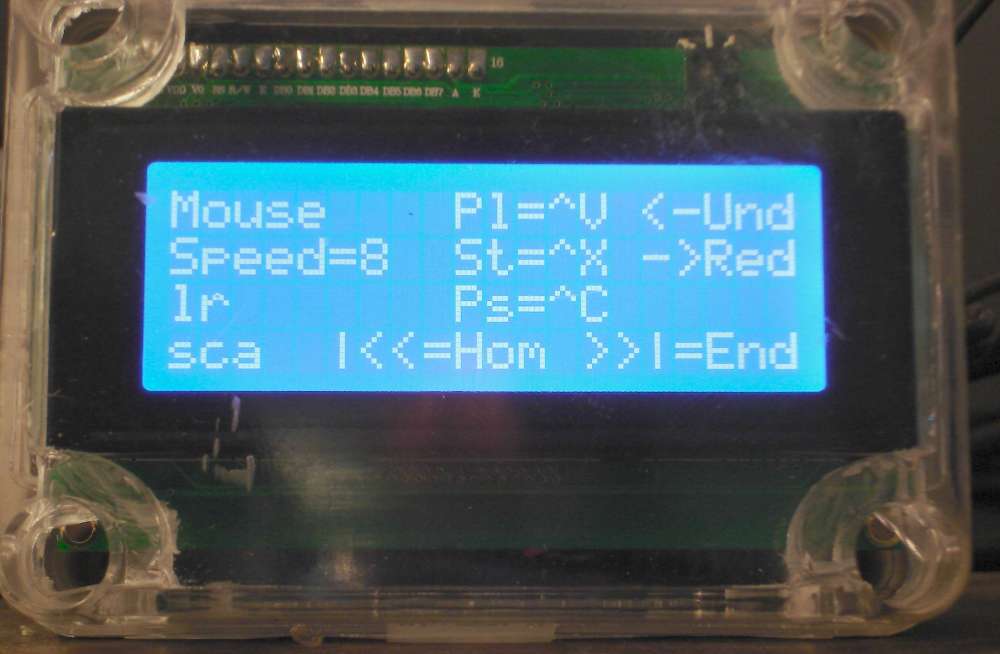
Mouse Mode Display
The device had three modes of operation. In mouse mode you could move the mouse up, down, left, right and all 4 diagonal directions. You could left click, right-click, scroll wheel and you can also left drag or right drag. You can also toggle the control, shift, or alt keys by pushing a particular button. The display on mouse mode really didn’t tell you much except for the status of the control, shift, or alt keys and the speed at which you move the mouse. The “lr” changes to “Lr” or “lR” if you are dragging with the left or right buttons respectively. The “sca” change to uppercase if you are toggling the Shift, Control, or Alt keys respectively. The other strings of text shown on the screen are some universal keyboard commands that work in mouse or arrow modes. They are only on the screen to remind me which buttons do which functions. For example the text “Pl=^V” reminds me that the “Play” button on the remote sends a “ctrl-v” which is the same as a “Paste” function.
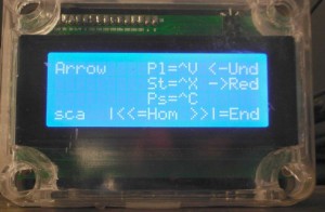
Arrow Mode Display
In arrow key mode the arrows on the TV remote don’t move the mouse, they move the arrow keys. This has been an especially useful feature for me when selecting large numbers of files in Windows Explorer. To do it with voice control I would select the first file an attempt to say the phrase “press shift down” dozens of times to select a bunch of files. If you accidentally mispronounce that phrase or if it misunderstands you it can do something completely different and you have to start over. This image shows arrow mode which again doesn’t really show you much except the status of the control, shift, alt keys and the reminders of other program keys.
Finally there is a full keyboard mode and that is the reason we needed the 20×4 character LCD display. In this mode there is a blinking cursor that you move around on the screen and when you get to the key that you wish to press you hit the select button on the remote and it types that key. It can type any key that is normally available from a standard PC keyboard including function keys and any combination of control, shift, and alt keys. This was really more of a proof-of-concept than a practical application but there have been times when everything else on my PC was locked up and I could type commands using this mode. I even plugged this device into my Raspberry Pi when doing the initial configuration although it was a bit tricky to type in the passwords before the session timed out. Here is an image of keyboard mode.
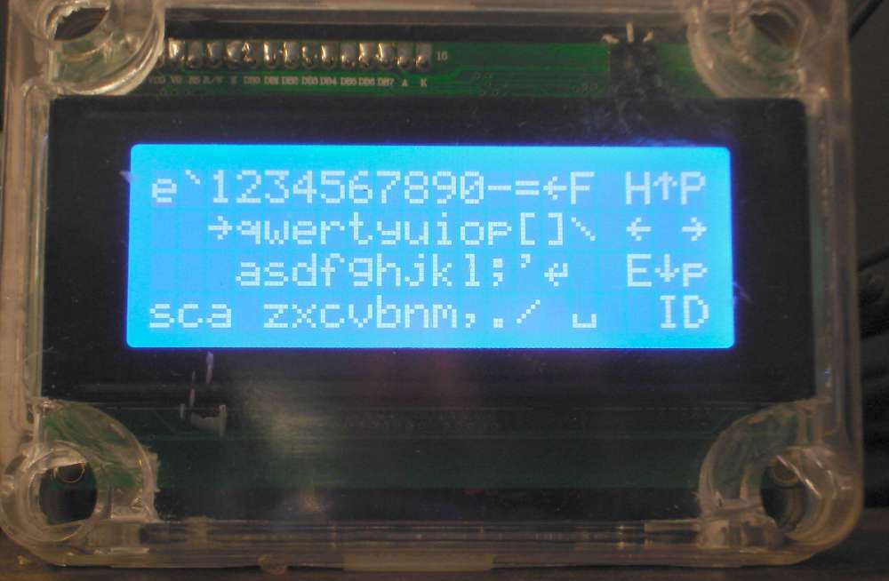
Keyboard Mode Display
Here is a YouTube video that I created for the weekly Adafruit Google+ Hangout Show-and-Tell where I demonstrate the various uses of my device. Unfortunately technical difficulties prevented me from showing this video on the live chat however you can see the video below and you can also click on the Show-and-Tell icon on the left to see the actual Google+ Hangout where I attempted unsuccessfully to show the video.
Sometimes Smaller is Better
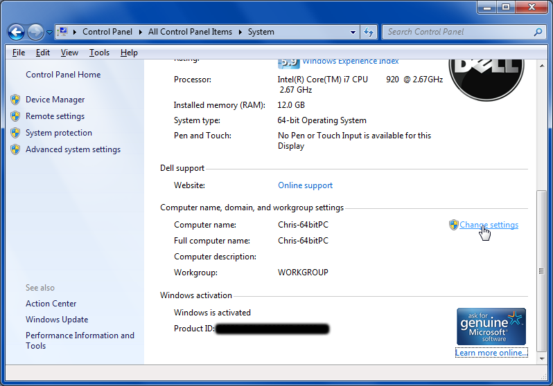
Recently I purchased a new Windows 8 laptop from Dell. I knew I needed to make another IR mouse but I didn’t want something as big and bulky as a full-size Leonardo and a 20×4 character display. I really didn’t need the keyboard mode. It was more just a proof-of-concept. I really only needed mouse and arrow key mode. I thought perhaps I could get by with just a few indicator LEDs to let me know if I was dragging the mouse or if the control, alt, or shift toggles were on.
Fortunately the technology has improved yet again since I built my first mouse and keyboard emulator. There is an even smaller Arduino available known as the Arduino Micro. It was designed by our friends at Adafruit Industries. It uses the same ATmega32u4 chip that the Arduino Leonardo uses. It is essentially a miniature Leonardo and it can also be used as a mouse and keyboard emulator. Here’s what it looks like…
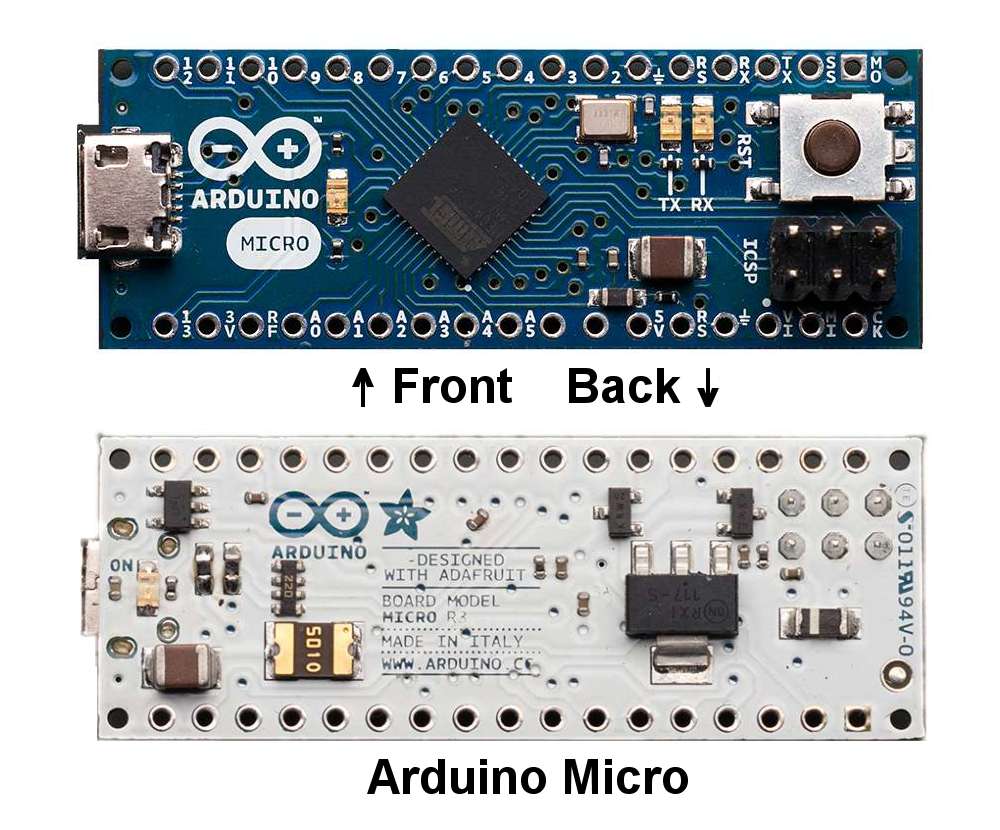
Arduino Micro: a mini Leonardo
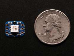
Adafruit RGB LED NeoPixels
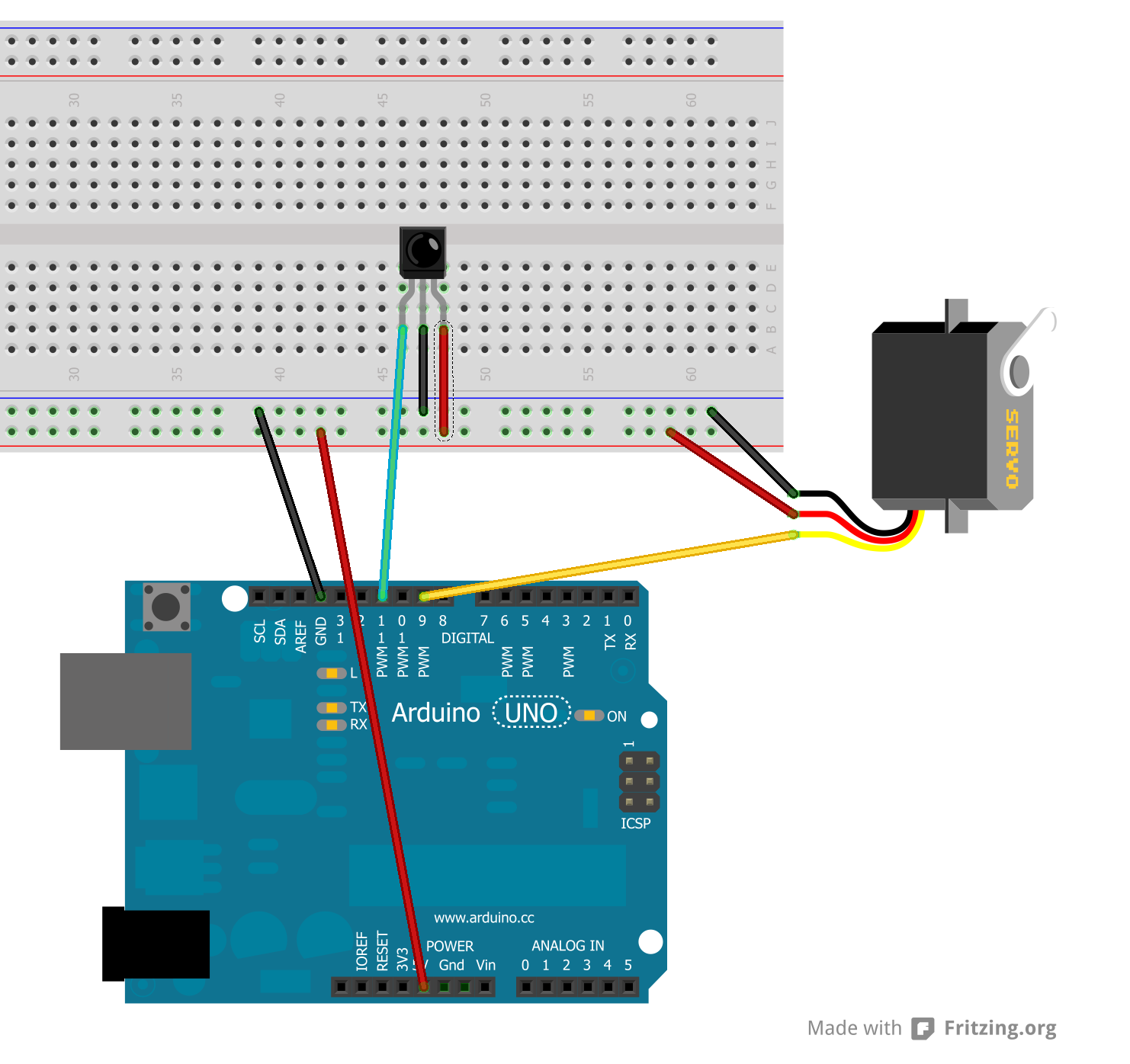
I still needed some sort of indicators to show me if I was holding down the shift, control, or alt and if I was dragging with the left or right mouse button. I would also need an indication if I was in mouse mode or arrow mode. This was a total of six indicators. Rather than wire up six individual multicolored LEDs complete with current limiting resistors and to take up six output pins, I decided to use two of these tiny Adafruit NeoPixel RGB LEDs. You can string dozens of them together and control them all with a single control wire. Add the +5v and ground wires and thus you only need three wires for an entire strand. The driver chip in each pixel controls the current so you don’t need to add resistors or anything. Since they are RGB I decided I can get by with just two of them. The wiring diagram below shows two of the pixels and an IR receiver wired into the back side of the Arduino Micro.
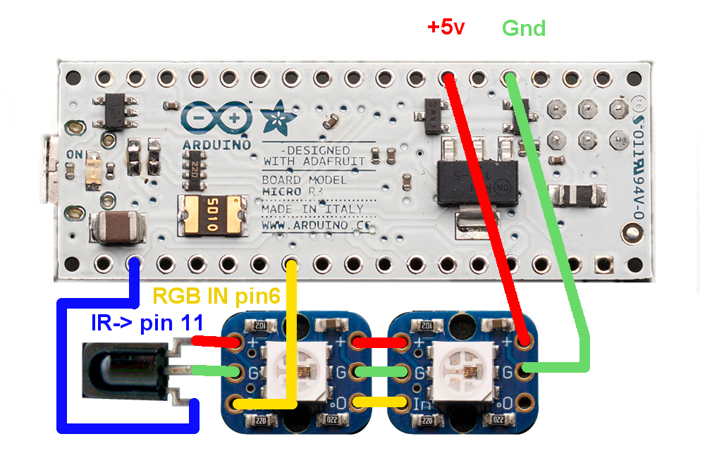
Wiring Diagram for IR Mouse
I placed a piece of double stick tape on the backside of the Micro and stuck the IR receiver and pixels onto the back of it. Arranging the parts in this particular way made it very easy to wire up the circuit. Here is an image of the completed device.
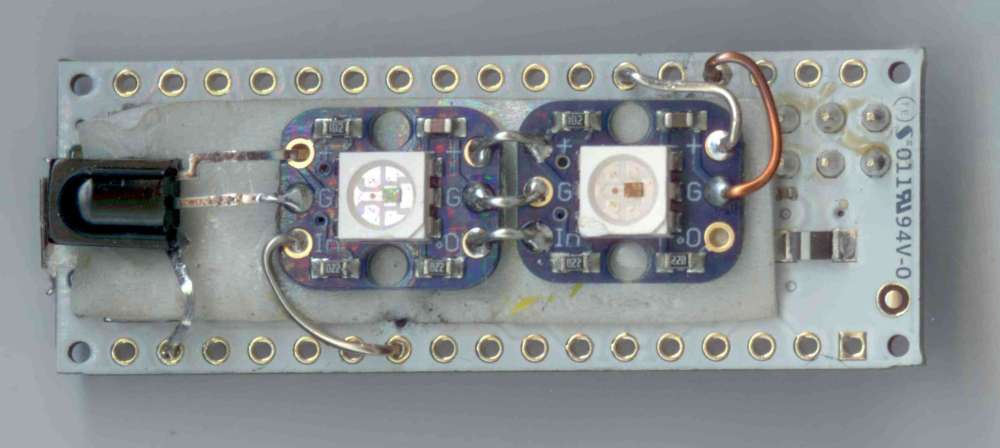
Completed Project
At some point I will probably cover the exposed wires with some hot glue or perhaps encase the entire device in some Sugru putty. I will need to maintain access to the six pins on the front side in case I ever want to rewrite the boot loader and access to the reset button might be necessary.
This new miniaturized person of my IR mouse not only helps me with my computer in light of my disability but it could be a useful gadget for anyone to use. Although you can purchase IR mouse controllers from a variety of sources, it’s always more fun to build your own and you can custom program in additional features not available in the commercially available products. For example if you are controlling a PowerPoint presentation on a projection monitor you might want to be free to move around the room while talking and using a small IR remote to click on the next image or do various other functions.
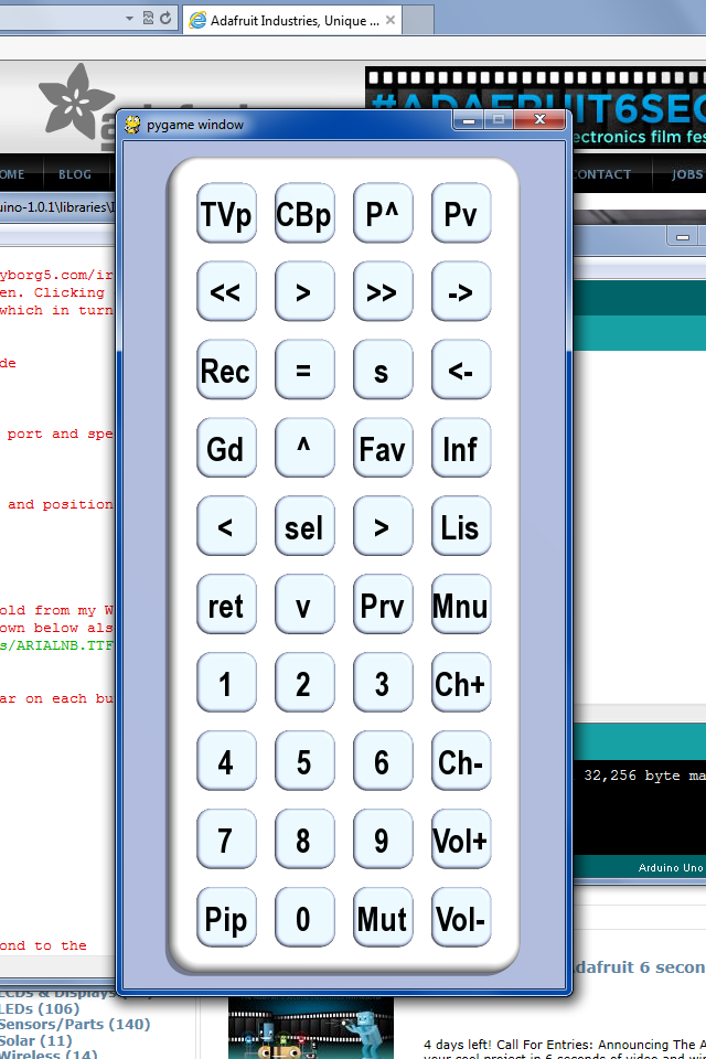
You can use any IR remote control such as a TV, DVD etc. to control the mouse as long as it uses a protocol that IRLib can understand. For this tutorial we are going to use a mini remote from Adafruit. It has 21 buttons and uses the NEC protocol. It’s small pocket-sized would make it ideal for controlling a PowerPoint presentation. Here is what the remote looks like
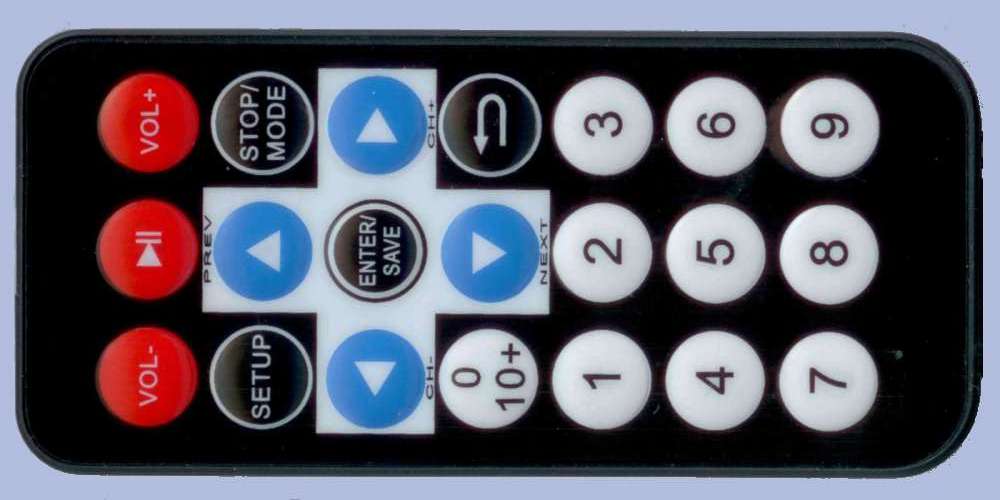
Adafruit Mini Remote
Programming the Commands
That takes care of the hardware. Now we need to write some software. We have 21 buttons available on this remote. Obviously we want to assign the mouse directions to the four arrow buttons. The four buttons diagonally from these arrows are an obvious choice for moving the mouse diagonally. And in arrow mode those corner buttons are obviously a good choice to assign the Home, End, Page Up, and Page Down functions. Among the other mouse functions are left and right click, left and right drag, faster or slower mouse movements, and scroll wheel up and down. Other arrow mode functions will include Backspace, Space, Escape, Tab, and a GUI key such as the Windows key. You can modify the program to put any command in any of these slots. This is just a suggestion.
Several of the buttons operate identically in either mouse or arrow mode. The top row of buttons toggle the Alt, Control, and Shift keys. The “Mode” button toggles between mouse mode and arrow mode. The “Release” button releases all held mouse buttons and toggle keys. Here is a graphic which shows which of the buttons on the remote performed which functions in either mouse mode or arrow mode.
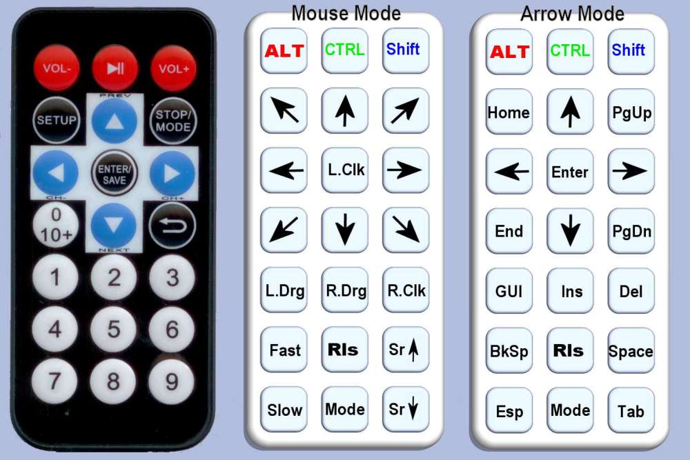
Assigning Commands to Buttons
One of the RGB pixels will show red, green, or blue if the Alt, Control, or Shift toggles are on. The other pixel shows blue when the left mouse button is dragging and read when the right mouse button is dragging. It shows green when you are in arrow mode.
The NEC protocol we are using sends a special code of 0xffffffff as a repeat code whenever you hold down a button. In order to process this we will always store any received codes so when we receive the repeat code we know what function to repeat. However the toggle keys should not be repeated without lifting off of the button so we have zeroed out the previous code when pressing one of those toggles.
Here is a complete listing of the code.
/* Example program for from IRLib – an Arduino library for infrared encoding and decoding

 * Version 1.1  April 2013 by Chris Young http://tech.cyborg5.com

 * "IRmouse" Control a PCs mouse or arrow keys using an IR remote

 */

#include

#include

#include

//The IR codes shown below are for the Adafruit mini remote

//which uses an easy protocol. The comments after each code refer to the buttons

//on that remote and not to their actual function on this device.
//Codes used by both mouse and arrow modes
#define CodeAlt 0xfd00ff //Vol-
#define CodeCtrl 0xfd807f //Play/Pause
#define CodeShift 0xfd40bf //Vol+
#define CodeRls 0xfda857 //5
#define CodeMode 0xfd9867 //8
//Used by mouse and arrow but have different meanings
#define CodeUp 0xfda05f //Up arrow
#define CodeDown 0xfdb04f //Down arrow
#define CodeLeft 0xfd10ef //Left arrow
#define CodeRight 0xfd50af //Right arrow
//Used only in mouse mode
#define CodeUpLf 0xfd20df //Set up
#define CodeUpRt 0xfd609f //Stop/mode
#define CodeLfClk 0xfd906f //Enter/save
#define CodeDnLf 0xfd30cf //0 10+
#define CodeDnRt 0xfd708f //Repeat
#define CodeLfDrag 0xfd08f7 //1
#define CodeRtDrag 0xfd8877 //2
#define CodeRtClk 0xfd48b7 //3
#define CodeFaster 0xfd28d7 //4
#define CodeScrUp 0xfd6897 //6
#define CodeSlower 0xfd18e7 //7
#define CodeScrDn 0xfd58a7 //9
//Arrow mode only
#define CodeHome 0xfd20df //Set up
#define CodePgUp 0xfd609f //Stop/mode
#define CodeEnter 0xfd906f //Enter/save
#define CodeEnd 0xfd30cf //0 10+
#define CodePgDn 0xfd708f //Repeat
#define CodeGUI 0xfd08f7 //1
#define CodeInsert 0xfd8877 //2
#define CodeDelete 0xfd48b7 //3
#define CodeBkSp 0xfd28d7 //4
#define CodeSpace 0xfd6897 //6
#define CodeEsc 0xfd18e7 //7
#define CodeTab 0xfd58a7 //9
#define Bright 16 //brightness of pixels
#define MOUSE_MODE 0
#define ARROW_MODE 1
#define MAX_MODE (ARROW_MODE+1)
#define MOUSE_LED 0
#define SHIFT_LED 1
Adafruit_NeoPixel strip = Adafruit_NeoPixel(2, 6, NEO_GRB + NEO_KHZ800);//Output pin 6
IRrecv My_Receiver(11); //Input pin 11
IRdecodeNEC My_Decoder;
int Speed;
int Current_Mode;
char Control_State;
char Shift_State;
char Alt_State;
long Previous;
uint32_t Shift_Status, Mouse_Status;
void UpdateStatus () {
Mouse_Status=0;
Shift_Status=0;
strip.setPixelColor(MOUSE_LED,Bright*Mouse.isPressed(MOUSE_LEFT),Bright*Current_Mode,Bright*Mouse.isPressed(MOUSE_RIGHT));
strip.setPixelColor(SHIFT_LED,Bright*Alt_State,Bright*Control_State,Bright*Shift_State);
strip.show();
};
//This Change_Mode routine is overly complex but it's a holdover from earlier code
//where I had three modes instead of two. Note we do not want to repeat feature
//on this function or on the toggle functions so we set Previous=0
void Change_Mode () {
Current_Mode=(++Current_Mode) % MAX_MODE;
Previous=0; UpdateStatus(); delay(500);
};
void setup() {
strip.begin(); strip.show();
Shift_Status=0; Mouse_Status=0;
My_Receiver.enableIRIn(); // Start the receiver
Current_Mode=0;
Control_State=0; Shift_State=0; Alt_State=0;
Speed=8; Previous=0; UpdateStatus();
Mouse.begin();
}
void Toggle_Mouse(int Button) {
if(Mouse.isPressed(Button)) Mouse.release(Button);
else Mouse.press(Button);
Previous=0; UpdateStatus(); delay(500);
}
void Mouse_Mode() {
switch (My_Decoder.value) {
case CodeLeft: Mouse.move(-Speed,0,0); break;
case CodeRight: Mouse.move( Speed,0,0); break;
case CodeUp: Mouse.move(0,-Speed,0); break;
case CodeDown: Mouse.move(0, Speed,0); break;
case CodeUpRt: Mouse.move( Speed,-Speed,0); break;
case CodeUpLf: Mouse.move(-Speed,-Speed,0); break;
case CodeDnLf: Mouse.move(-Speed, Speed,0); break;
case CodeDnRt: Mouse.move( Speed, Speed,0); break;
case CodeLfClk: Mouse.release(MOUSE_LEFT); Mouse.click(MOUSE_LEFT); delay(400);break;
case CodeRtClk: Mouse.release(MOUSE_RIGHT); Mouse.click(MOUSE_RIGHT); delay(400);break;
case CodeLfDrag: Toggle_Mouse(MOUSE_LEFT); break;
case CodeRtDrag: Toggle_Mouse(MOUSE_RIGHT); break;
case CodeFaster: Speed=min(30,++Speed); delay(100); break;
case CodeSlower: Speed=max(1,--Speed); delay(100); break;
case CodeScrUp: Mouse.move(0,0,1); delay(100); break;
case CodeScrDn: Mouse.move(0,0,-1); delay(100); break;
};
};
void Toggle_Key(char *Toggle,char Key) {
if(*Toggle){
Keyboard.release(Key); *Toggle=0;
}
else{
Keyboard.press(Key); *Toggle=1;
};
Previous=0; UpdateStatus(); delay(500);
};
//Releases all held mouse buttons and toggle keys
void Release_All() {
Keyboard.releaseAll();
Mouse.release(MOUSE_LEFT); Mouse.release(MOUSE_RIGHT); Mouse.release(MOUSE_MIDDLE);
Alt_State=0; Control_State=0; Shift_State=0;
UpdateStatus();
};
//In my experience some keys work better if you put a little extra delay.
void Key_Press (char Key,int D) {
Keyboard.write(Key); delay(150+D);
}
void Arrow_Mode() {
switch (My_Decoder.value) {
case CodeLeft: Key_Press(KEY_LEFT_ARROW,0); break;
case CodeRight: Key_Press(KEY_RIGHT_ARROW,0); break;
case CodeUp: Key_Press(KEY_UP_ARROW,0); break;
case CodeDown: Key_Press(KEY_DOWN_ARROW,0); break;
case CodeInsert: Key_Press(KEY_INSERT,0); break;
case CodeEnter: Key_Press(KEY_RETURN,100); break;
case CodeBkSp: Key_Press(KEY_BACKSPACE,100); break;
case CodePgUp: Key_Press(KEY_PAGE_UP,200); break;
case CodePgDn: Key_Press(KEY_PAGE_DOWN,200); break;
case CodeHome: Key_Press(KEY_HOME,0); break;
case CodeEnd: Key_Press(KEY_END,0); break;
case CodeGUI: Key_Press(KEY_LEFT_GUI, 100); break;
case CodeSpace: Key_Press(32, 100); break;//ASCII space
case CodeEsc: Key_Press(KEY_ESC, 100); break;
case CodeTab: Key_Press(KEY_TAB, 100); break;
};
};
/*
//You can uncomment and use this routine to send control characters such as
//control-z for an undo button or control-c for copy etc.
void Send_Control(char Key,int D) {
Release_All(); Keyboard.press(KEY_LEFT_CTRL);
Keyboard.write(Key); Release_All();delay(150+D); Update ();
}
*/
void loop() {
    if (My_Receiver.GetResults(&My_Decoder)) {
       My_Decoder.decode();
//Adafruit remote uses NEC protocol which sends a special repeat code
//if you are holding down the same button. We store each received code
//in "Previous" so that we can properly handle repeat codes.
if(My_Decoder.value==0xffffffff)
My_Decoder.value=Previous;
else
Previous=My_Decoder.value;
switch(Current_Mode) {
case MOUSE_MODE: Mouse_Mode(); break;
case ARROW_MODE: Arrow_Mode(); break;
}
switch (My_Decoder.value) {
case CodeMode: Change_Mode(); break;
case CodeAlt: Toggle_Key(&Alt_State,KEY_LEFT_ALT); break;
case CodeShift: Toggle_Key(&Shift_State,KEY_LEFT_SHIFT); break;
case CodeCtrl: Toggle_Key(&Control_State,KEY_LEFT_CTRL); break;
case CodeRls: Release_All(); break;
};
My_Receiver.resume();
}
}
For reference purposes here’s a link to the documentation on the keyboard and mouse libraries for use with Leonardo or other comparable Arduinos.
http://arduino.cc/en/Reference/MouseKeyboard
You will also need the special library for Adafruit RGB NeoPixels which can be downloaded from GitHub.
https://github.com/adafruit/Adafruit_NeoPixel
Simply download and unzip the library into your library folder.
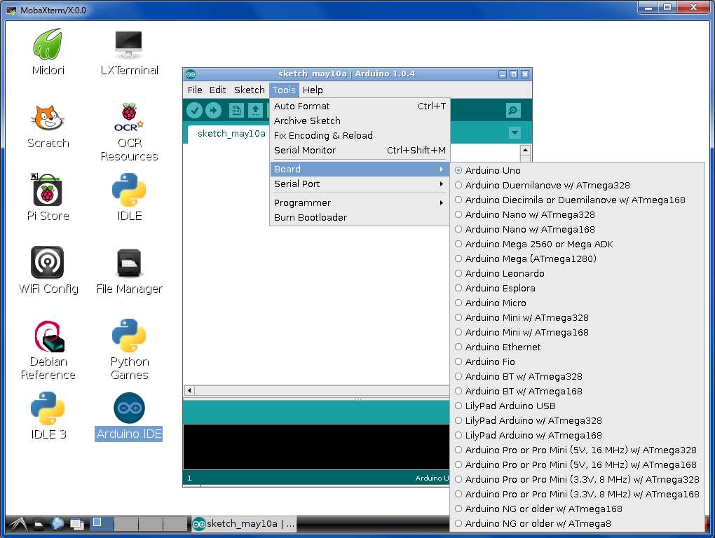
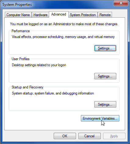
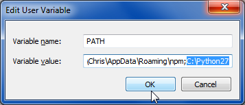
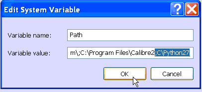
Note that the latest Arduino IDE (version 1.0.5 as I write this) lists the Arduino Micro as one of the boards it supports. When using either the Leonardo or Micro you will need a special driver for Windows computers. This driver is available in the driver’s library of the latest Arduino IDE. The latest drivers combine drivers for all of the supported boards into a single Windows 8 compatible signs package.
Simply plug the Arduino Micro into the USB port, upload the sketch, and then point your remote at the receiver. The device initializes into mouse mode so you should be able to move the mouse around using the arrow keys. Try switching to arrow mode using the “Mode” button. Go back to mouse mode and try pressing the faster or slower buttons. You won’t notice anything while pressing them however subsequent mouse movements will be faster or slower.
Here are links to the hardware mentioned in this tutorial:
Here are links to hardware used in the original IR mouse and keyboard emulator. At some point I will clean up the code on that project and publish it. If you have an immediate use for such a device, feel free to contact me and I will give you what I have but for now it’s not really fit for public consumption.