Comfort Fit for a King

In this installment we will cover the remainder of the first week of working on the new wheelchair. We work on getting the more comfortable and trying to diagnose what went wrong with the programming that has disabled my new joystick.


Are You Comfortable?

There is an old vaudeville joke where a nurse is working with a patient and she says “Are you comfortable?” The patient replies “Ehhh… I earn a living… But not really comfortable”. I’ve used that joke in my life more times than I can count. I guess it’s an indication that friends and family often look at me and are concerned about my comfort. I probably look uncomfortable 99% of the time. My scoliosis has left me with two 90 degree bends in my spine. My joints all have severe contractures. My normal driving position in my wheelchair leaves my head tilted sideways a good 45 degrees. My arm was always propped up in an awkward position. Most of all I’m fortunate enough to have a lot of people who care whether or not I am comfortable. So when these kind people inquire about my comfort, I always pull the joke and say “I earn a living”.

Somewhere along the way I quit using the joke. Either it just got old, or I got tired of it, or perhaps subconsciously the inaccuracy of it began to bother me. My only income is from Social Security Disability payments. So the statement “I earn a living” isn’t particularly accurate. The sentiment of the joke that “I get by okay even though I’m not plush financially” is accurate. The real question is “Why can’t I answer the question directly?” Why can’t I respond yes or no to “Are you comfortable?” I was blessed to have my friend Rick Ruiz as my home health aide for three years. Somewhere along the way I started answering his “Are you comfortable?” inquiries honestly by saying “I’m not comfortable… But I’m okay”. This wasn’t a financial joke. I explained to Rick on a number of occasions that I never really am comfortable regardless of what position I am currently sitting. When he asks if I’m comfortable and I am as comfortable as I get I can say “I’m okay” but I can’t honestly say “I’m comfortable”. It was a stark realization and admission that I never really was physically comfortable in my normal position. But my comfort really didn’t matter because it was the only position in which I could sit and still be able to operate my wheelchair.

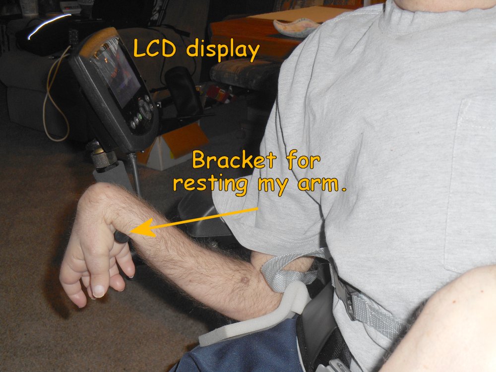
Ever since my arms finally gave out some time last summer and I could no longer drive my wheelchair, I began to adjust my normal sitting position. Rather than prop my right elbow on top of the control box, I begin tucking it in behind the box. My wrist would hang off to the right side against the armrest and it left my fingers free to hold my little pushbuttons for my ultimate remote. That left my body in a much more upright position. I began putting my head against the headrest which I normally did not do. The headrest was mostly used while riding in my van. In fact that was the original reason for adding a headrest to my wheelchair many, many years ago. Eventually I began leaving the headrest in given what I was not riding in the van because I did occasionally lean back against it. The problem was that the headrest was not in the proper “sitting around the house position”. It was only useful when I was sitting with my chest strap extremely tight in my “riding in the van” sitting position. I eventually found a way to sort of balance my head on the corner of my headrest for my normal sitting position. The discomfort of the corner of the headrest digging into the back of my skull was considerably less than the discomfort of having my head tilted sideways at a 45 degree angle all of the time. So with the elbow tucked in, and my head balanced on the corner of the headrest, for the first time in a very, very long time I was (choking on the words more comfortable) less uncomfortable.

Unfortunately there were consequences to sitting in this new position. My wrist began getting sore where it leaned against the armrest. We compensated by getting a little piece of curved cardboard that fit my forearm perfectly. We tried gluing it on to the armrest but my arm would change pay position from time to time and the glue would not stick anyway. We finally just got to the point where we would stuff it underneath my arm as needed. That worked well for several months. Then I started having problems with my armpit and chest area right above my nipple. With my elbow always tucked in instead of high up atop the control box, my back brace was digging into my chest differently than it had for God knows how many years. I’ve made minor adjustments in the way I put the brace on and I’ve taken to applying some analgesic cream to the area each morning. I am managing that situation reasonably well but there have been many days where I’ve had to put my arm up and down sometimes every 15 or 20 minutes. I tried putting a pillow under the elbow but that threw everything off and made my wrist go numb.

Another consequence of the loss of the use of my arms has a potential effect on my normal attire. For over 30 years I’ve not worn long sleeve shirts. Even if they were lightweight, the sleeve would impact my arm sufficiently enough that I could not drive. I’m not been able to drive with a coat or jacket on for many, many years. But a few months ago I was visiting my sister’s house and they tend to keep the place considerably cooler than I normally like. Dad knows to wear a sweatshirt whenever we go there. So one day I was sitting there freezing my ass off and it occurred to me there was nothing to keep me from wearing long sleeves anymore. And the way that I intended to drive the new wheelchair was not going to be impeded by long sleeves. I need to go shopping for sweaters, sweatshirts, and perhaps a long sleeve dress shirt. I don’t own any and haven’t for years. Even my good shirt that I wear on the rare occasions I dressed in a suit and tie is a short sleeve shirt.

That was the state-of-the-art from sometime in late summer last year up until the new wheelchair arrived. One of the things that had made me reluctant to get a new chair for many years was the idea that I was going to have trouble adjusting to it and getting at least as comfortable as I was in the old chair. All of the constraints to my comfort such as needing to be able to drive were now gone. In the months waiting for the new chair, there were things I might have done to the old one to make it more comfortable such as redesigning the headrest. However that would’ve been wasted effort on a chair that I was destined to put in mothballs sometime soon. Dad and I often talked about the fact that once the wheelchair came, it might be a very long time until we got me “comfortable” or at least “okay”. I’ve been sitting in the same position in the same chair for so many years that any changes that have consequences. This was proven by the fact that sitting in my old chair in a different position had had consequences. But at least with the new chair we could start to address the problems and not have them wasted effort.


Mushy Butt

roho low-profile
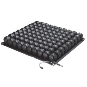
A key element of my comfort is something called a Roho seat cushion seen on the right. It is an inflatable seat cushion with rows and columns of blob shaped chambers. When you sit on it, the air flows from one chamber to another until the pressure equalizes. Over the years I had tried a variety of foam cushions, gel-filled cushions and I forget what other options but the Roho was the only thing that really worked consistently. I use of problems with them springing a leak every few months but when we replaced the cushion completely one time, we ordered it with a nylon cover. Either they started making the cushions more durable or the cover really protected it well because the last cushion I had lasted for more years that I can remember.

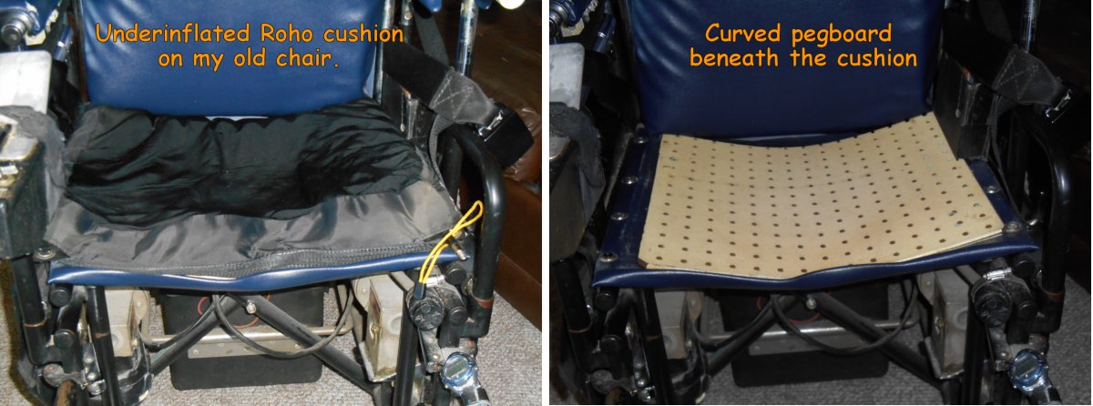
When I did my test drives in the other wheelchairs we put my old Roho into the new chair. It wasn’t very comfortable at all. I normally keep the cushion barely inflated. I found that if I fill it up too much that it was too mushy. I felt sort of round bottomed as if I was going to tip over. But sitting in the demo wheelchair I was definitely not mushy enough. Because my existing Roho cushion is very old, we told them to order a new one. When the new chair arrived, what was supposed to be a “low-profile” version of the cushion looks a lot taller than the one that I was using. Even given the fact that I normally underinflated mine, it definitely is taller. The new model is called a Quadro version. The various cells are divided into four groups and there is a valve that you can close internally so that pressure cannot go from one group to the other. That was a feature I really didn’t need but it didn’t hurt anything. Well no that’s not exactly true. I later discovered that the valve which closes the four chambers from one another was poking me in the back of the leg. We just turned the cushion around so it’s at the back and there was no problem.

Theoretically my normal underinflated cushion should have felt the same between my old chair and the demo chair. In the old chair there is a piece of Masonite pegboard under the cushion. That all sits on the curved Naugahyde seat of the wheelchair. Over the years the pegboard has warped considerably as you can see in the photo below. Both sides of the pegboard are about an inch and a half higher than the center. But in the new chairs, the seat is a solid piece of aluminum which is completely flat. Dad and I had already made plans that we might have to put some sort of curved surface between the flat metal seat and the new Roho. When the chair arrived we tried using the new Roho directly on the metal seat. It felt really good because we had it inflated much more than usual. I always start out with the seat overinflated and then gradually let air out until it’s where I want it. The first time I sat in the wheelchair the day they delivered it, it was surprisingly comfortable. I still felt very round bottomed and mushy butt but again the way I sit these days with my head in a fixed position and my chest strap and lap belt very tight, having a mushy butt sort of felt good.

roho_old

After a day and a half of sitting in the new chair I decided that the seat was going to need a bit of adjustment to compensate for that curve that I was used to. When sitting in the old chair, I did not sit in the middle of the seat. I would sit far off to the right side. That puts my right hip on the high part of the curve in my left hip in the middle of the dip. I concluded that I needed that little boost on the right side to compensate for the strange twist in my pelvis and lower spine. Dad cut a piece of plywood and made a wedge just for the right side. Here are some photos of the wedge and the new Roho sitting on top of it.

roho_new

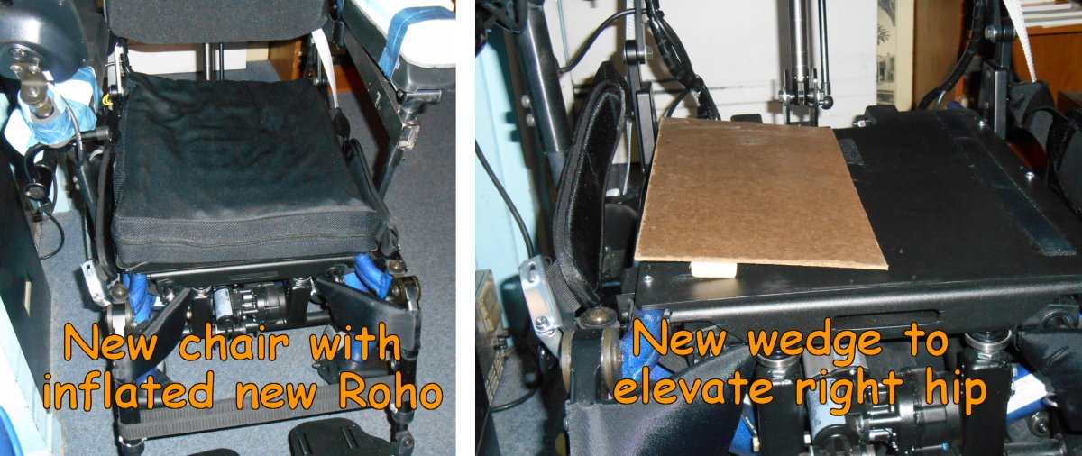
I mentioned that my Uncle Keith came by on Thursday and brought a bunch of parts from my cousin Nancy’s old wheelchairs. Dad installed one of the headrest that he brought and added a couple of extra pieces of foam to it in strategic places. He installed the wedge under the Roho cushion. Friday which was the fifth day of the new wheelchair was my first day of sitting in the new chair with the wedge under the cushion. It worked exactly as I had hoped. The new headrest was a keeper as well. On Saturday I sat in the old chair because I was planning on going to church Saturday night. We do not yet have the proper tiedown equipment for the new chair in the van. As it turned out the weather was nasty Saturday and I did not go to mass after all. But sitting in the old chair gave me quite a surprise. I can actually say that I was more comfortable in the new chair that in the old one.


Disaster Recovery

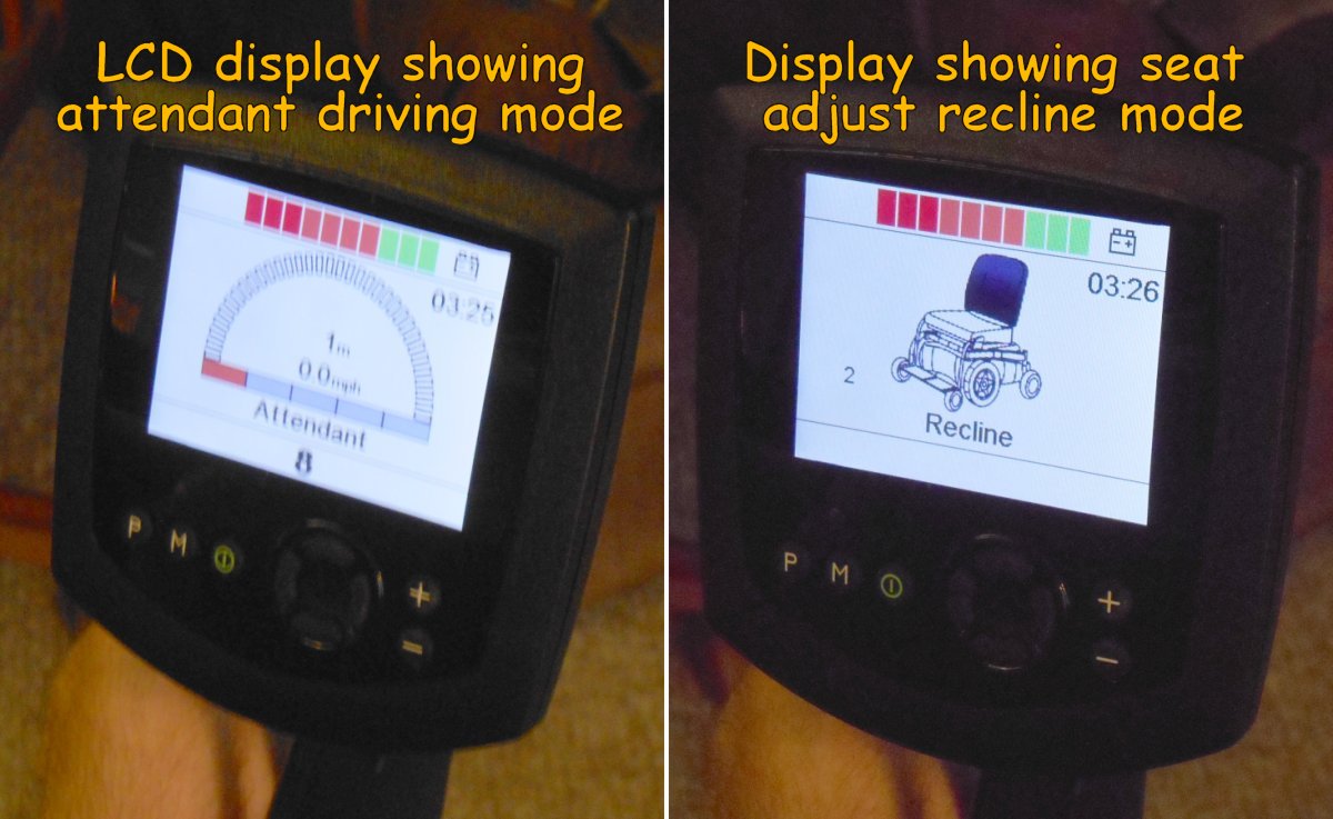
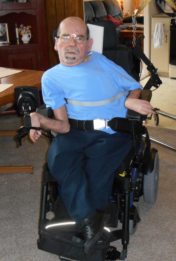
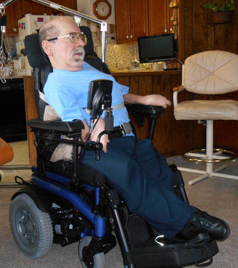
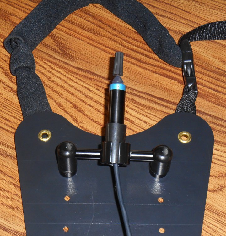
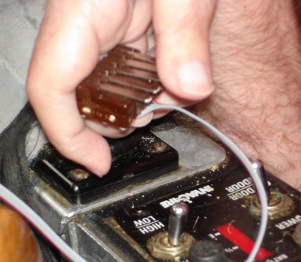
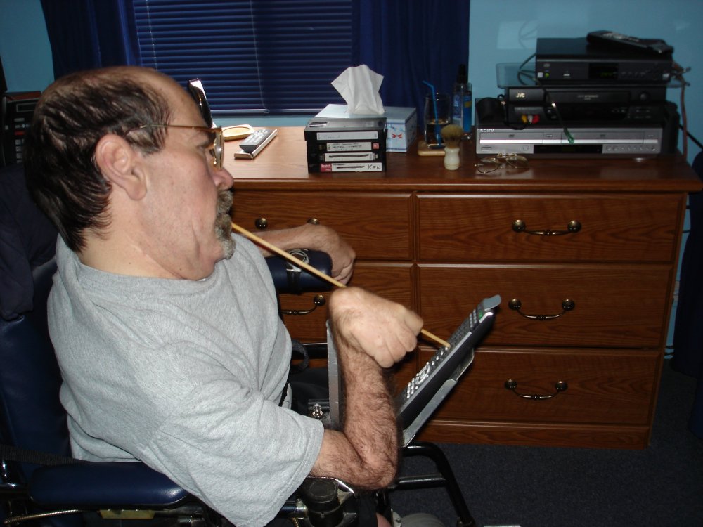
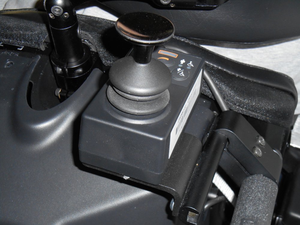
When I left off my previous installment of the blog we had just accidentally disabled the joystick and left the chair permanently stuck in attendant drive mode. Dad could drive me around the house using the joystick on the back of the chair which you can see below. But I couldn’t do anything with the chair myself. Furthermore it was stuck in such a condition that I could no longer get into the programming menus.

attendant

My mother was a great troubleshooter. She like to take a multi prong approach to problems. For example in an emergency she would call 911 and then would call our parish prayer chain. Learning from her example I tried multiple approaches as well. I sent an email to both Patrick and Aaron who were the wheelchair technicians who delivered the chair. I explained that we had been getting joystick error messages. I had tried to correct it by going into programming mode. Somehow we got locked out of programming mode and the joystick no longer works at all. We are stuck in attendant drive mode. I could’ve called them but I wanted to weigh out all the issues in writing so I was sure they would understand everything that was going on. I then started doing Google searches to see if I can find out something on my own.

I came across a wonderful website called wheelchairdriver.com. It is run by a guy in England who seems to know what awful lot about power wheelchairs. He has built several of his own and he has an online forum full of other people just like me. I posted a message describing my problem. They also have a section of the discussion forum for introductions so I wrote a brief bio of myself and posted links to my blog. They said literally “you’ll find this place full of people a lot like you”. As far as my technical question, it only took a couple of hours and I had several replies. They didn’t know what was causing the joystick error although they had some ideas. But they definitely knew what was wrong that I could no longer get into programming mode. They reassured me that I should not feel like an idiot. I was not the first nor would I be the last user to enter that forum having accidentally locked up their programming. That made me feel a little better.

It turns out that there are different levels and methods of programming a PG Drive Technology R-Net Onni wheelchair control system. I had been using the least capable (and one would think safest) level which is called onboard programming or OBP for short. The second level is called “dealer programming”. It uses a gadget called a “dongle” that dealers have which authorizes them to get into more things. Dealers also have a handheld device called a programmer that allows them to do various programming tasks. I think that may be for wheelchairs that did not have the LCD display that mine has but still needs some sort of programming or calibration. I’m not really clear on what the dongle does as opposed to the handheld programmer. The third level of programming is called OEM programming. It is for the people such as Sunrise Medical who manufacturer the Quickie wheelchairs but purchase the controller equipment from PG Drive Technology. The people in the forum weren’t exactly certain whether or not a dealer programmer would be sufficient to get me unstuck or whether I would need OEM programming.

One of the ways that you could reprogram the device is using a special USB cable and connecting it to a PC and using special software. So I began investigating the possibility. Naturally anything I could do by plugging something into a computer and doing it with software was going to appeal to me. I’m not capable of pushing the menu buttons on the LCD display but if we could plug my chair into my PC then I can use my voice control to operate any software. Google searches for such devices led me to a pricelist from some dealer saying that the devices cost about $400 or more. There were also a couple of units on sale on eBay for similar prices but one of them was up for bids at $180 with three days to go in the auction. Over the weekend I continued to bid against someone up to $225 but when it reached $250 and I wasn’t really sure if it would fix my problem I decide to drop out. It ended up going for about $300.

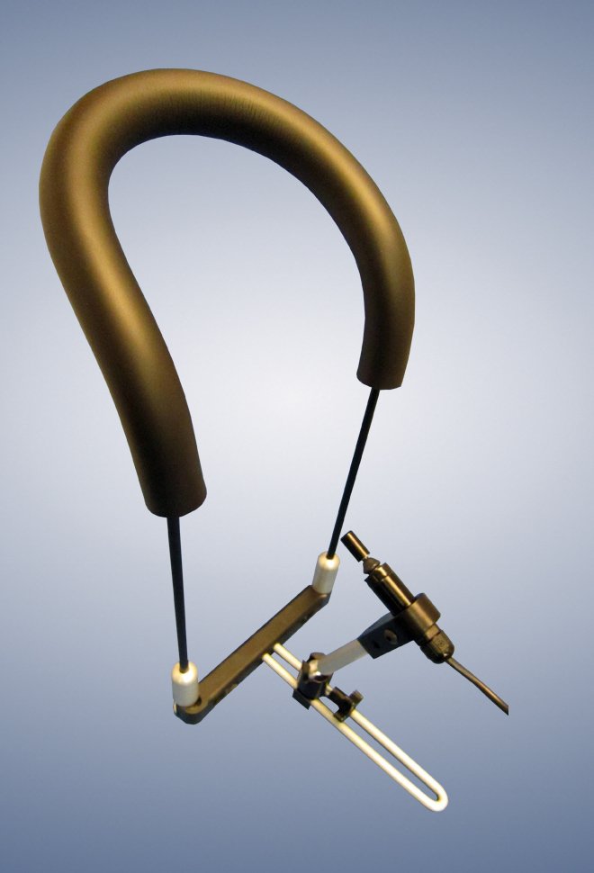
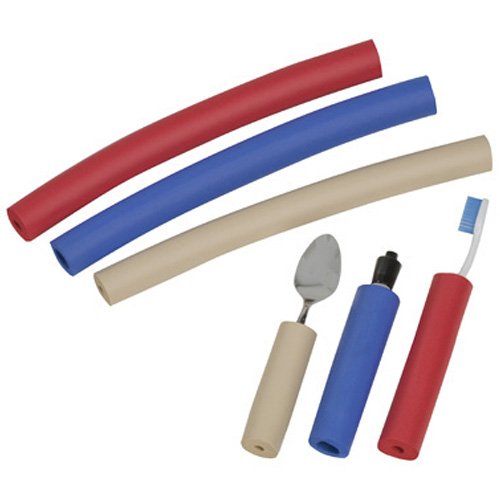
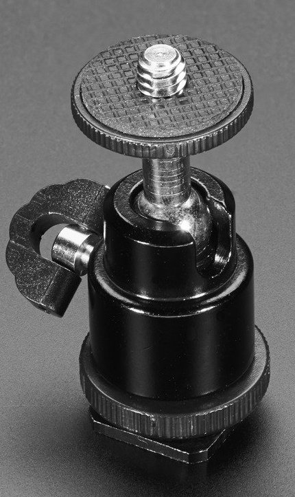
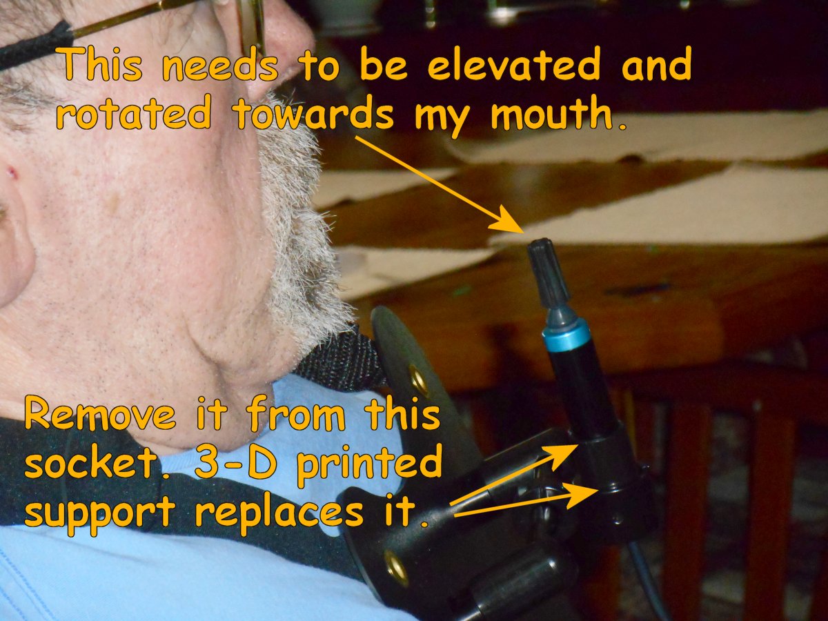
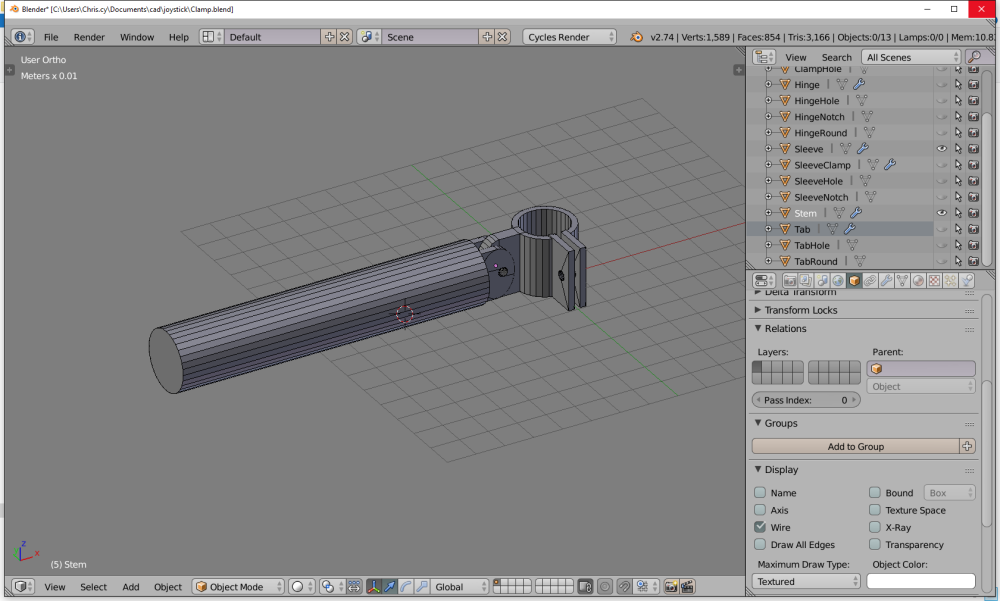
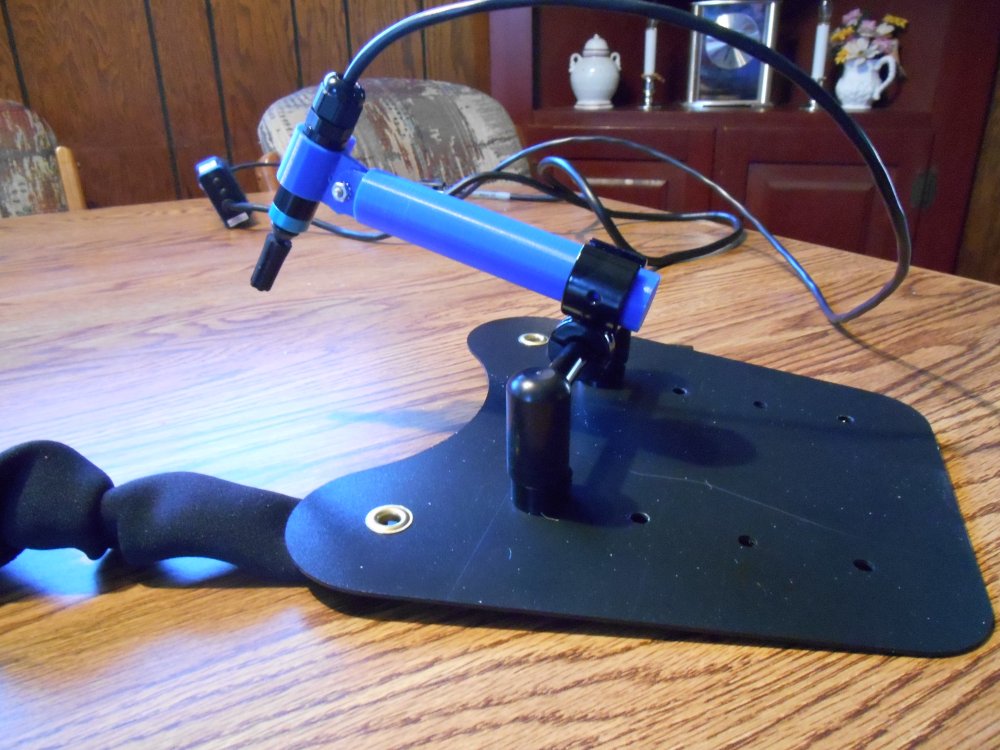
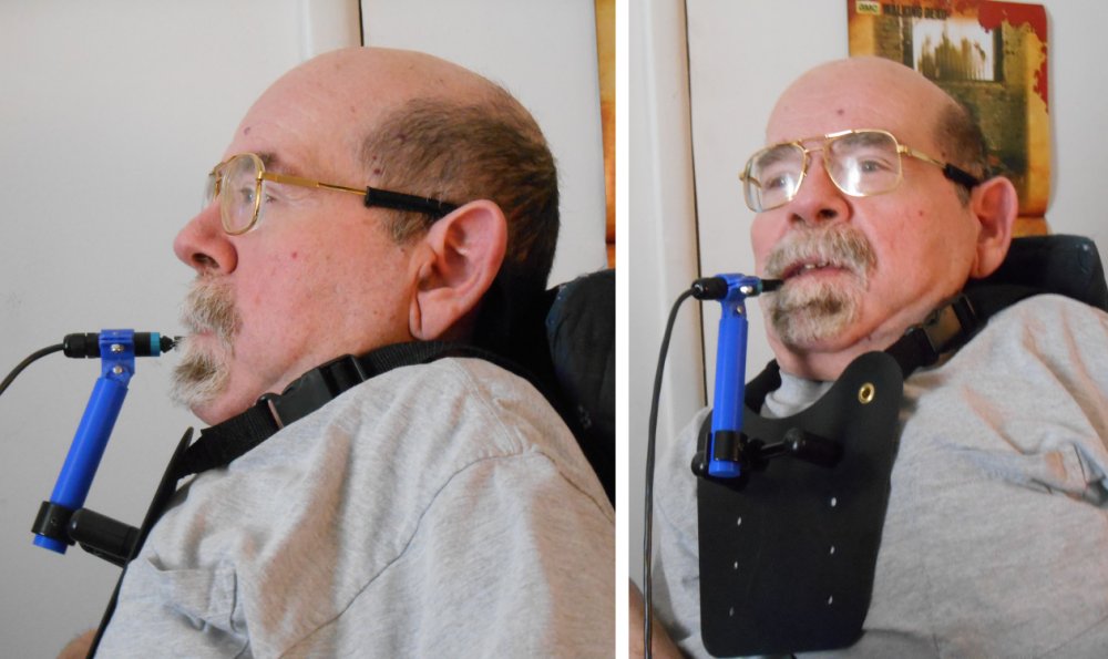
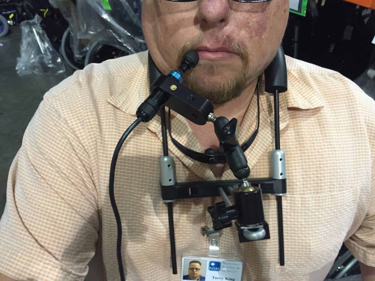
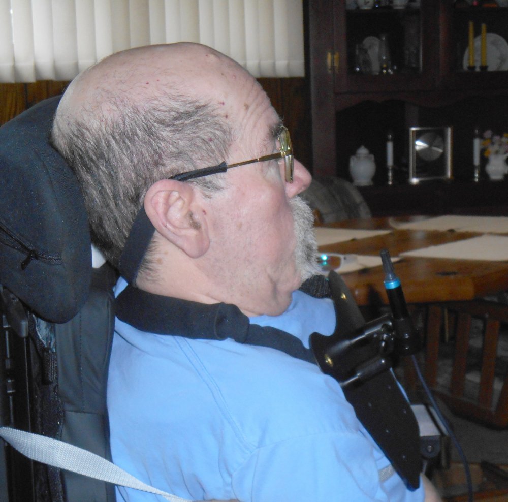
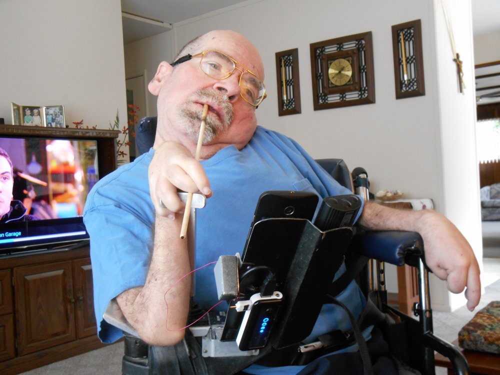
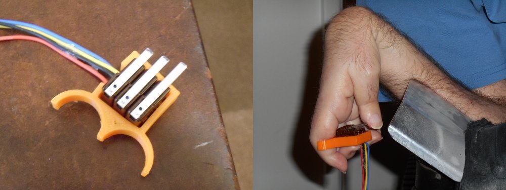
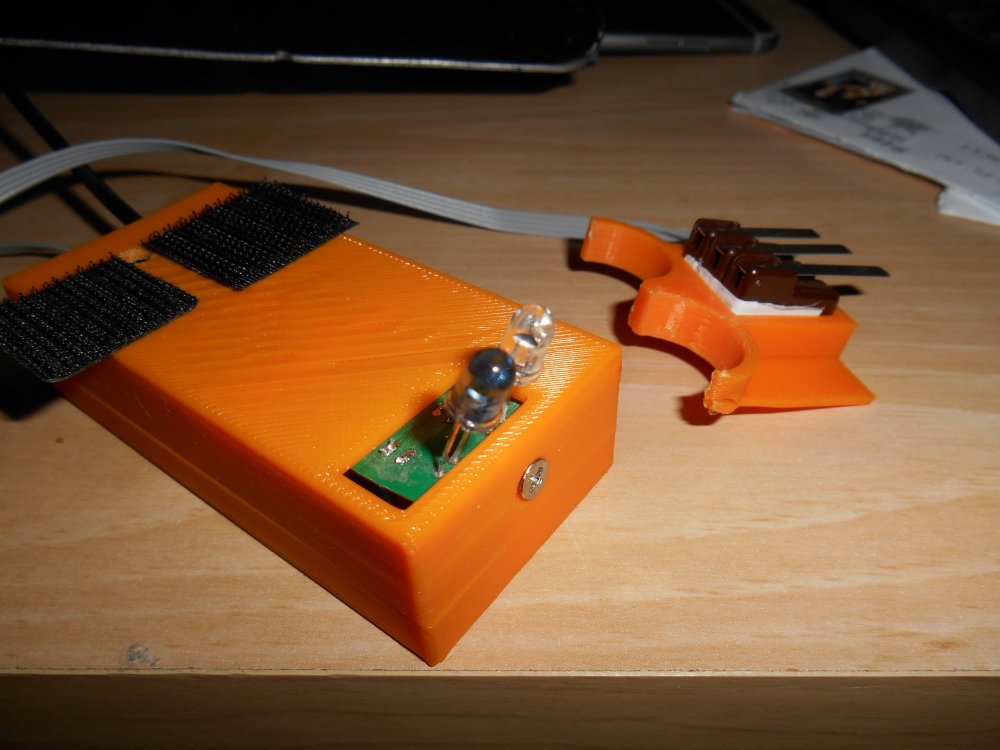
Also on that Friday my foam tubing arrived from Amazon. There were two pieces each of red, yellow, and blue foam of different diameters. Each piece was about a foot long. It turned out that the red foam was the proper diameter and a 1 foot piece was a little bit short. We plan to put two of them end to end perhaps gluing them together and then trimming the extra long piece to the proper length. We spent some time bending the bars and trying on the foam padded device. It looks as though it was going to work as well is the one we had use on the successful test drive. I didn’t really like using the bright red piece. I was hoping the blue one would work since TARDIS blue is my chair’s color scheme.

I spent the rest of the day working on the blog and catching up on TV. The week had gone by so quickly I have forgotten that I had tentative plans for the weekend to go see Batman vs. Superman with my friends Rich and Kathy. We had never finalized plans and there was some miscommunication about which weekend we were going. But I was so preoccupied dealing with the new wheelchair that I had totally forgotten about the movie. I sent an email to Rich and we made firm plans for the following weekend.

“Evening came and morning followed — the fifth day” Genesis 1:23


“It’s Good to Be King” – Not!!!

You might presume that I would tell you what happened on the sixth day and then I would quote Genesis 1:31 which is followed up by the explanation that on the seventh day God rested. Much to my disappointment I’m not God so I rested on the sixth and seventh day both. I monitored my losing eBay bids, swapped some more messages at the wheelchair support forum but mostly I just goofed off watching racing on TV and playing an online computer game.

For about nine years I’ve been playing a browser on the game called Travian. It is a strategy and tactics simulation where you build little villages, produce resources, train troops, form alliances, and attack your enemies. It takes about four months to play an entire round of the game. You log into the website several times a day and tell it what to build, who to attack etc. I first started playing the game when my mom had cancer. It was a little bit of fantasy escape to get my mind off of worrying about her. I made some good online friends and have lots of fun over the years. I haven’t played it continuously but I play it quite a bit. The new version called Travian Kingdoms is organized a bit differently in that you have some players who are called Kings and the remaining players are their governors. An alliance can have up to three Kings and an unlimited number of governors under them. I’ve always played an ordinary governor but in the current round we’ve had three Kings who have given up and left the game. Because I’m such an experienced player I had built more villages with larger population than anyone left in our group. Despite my best efforts to get someone else to volunteer, I got appointed to be the new King.

One of my favorite lines from Mel Brooks’s “History of the World Part 1” is when he says “It’s good to be King” with a cheesy grin on his face as his servants are waiting on him. Apparently Mr. Brooks never played Travian Kingdoms. Being King is a pain in the ass. You have got all of the responsibility of managing everything and it makes you a bigger target for people to attack. The guys and gals who were playing with me all told me I was doing a great job but I think they were more interested in the fact that they didn’t have to do it themselves. I had never played the King position before in the game and really didn’t know how to work the controls or what the requirements were. So I was learning by doing in a hurry. I would like to try being a King at the beginning of the game where I could plan for the strategy from the beginning. Taking over in the late stages of the game was a lot of work. But it did what Travian has always done for me. It took my mind off my troubles. In this case the trouble was I’m sitting in a $40,000 brand-new wheelchair that I had waited 10 months to get and somehow I managed to break the damn thing and the quickest I might get a solution would be Monday. So I blew the weekend being a King.

Good Days and Bad Days

In this installment we will cover the third and fourth days of working on the new wheelchair. We start to work on the new bib mount and continue to make other adjustments.


If the Shoe Doesn’t Fit…

We are now up to Wednesday which was the third day of the new wheelchair. We started out the day by sitting me in the new chair. Dad had previously shortened the foot rests so we were anxious to see how they fit. Somewhere along the way we miscalculated because both of the rest were still too low. For the time being we would put a pillow under my feet and dad would have to go back and get out the sawzall and shorten them even further.

The headrest wasn’t exactly like I wanted it but it was good enough to get me through the day. We would do more tinkering with that later. When the wheelchair technicians were here they had raised my left arm rest as high as it would go. It still wasn’t high enough but as a temporary measure we put a pillow under my left arm.


Getting In the Mode

There is an LCD display mounted on the right arm rest. The chair has various modes that you can put it in for driving indoors or outdoors or for using the attendant controls. It also displays an image of the seat when you are in seat adjustment mode so you know which part of the seat you’re adjusting. For example when you push the mode button it would say one of the following “recline”, “tilt”, “recline and foot rest”, “both foot rests”, “left foot rest”, “right foot rest”. If you moves the joystick forwards or backwards it moves that item. If you tap the joystick left or right it moves to the next seat item such as going from recline to tilt and so on. Of course until I get a mode change button, I wasn’t going to be able to operate any of this.

display

The LCD display was mounted pretty far forward sticking out in front of the armrest. It actually made the chair a little bit difficult to drive it through a narrow passage because it was sticking outside and so far forward. We would later adjust it so that it was not sticking outside or the front so far. When we got that adjusted, the little bar where the display is mounted actually is in a very good position where I can rest my right arm and still be able to hold the micro switches for my ultimate remote control.

armrest

I forgot to mention in an earlier post that I solved the mystery from the first day. When Patrick and tried to plug in the user control button for changing modes, it would turn the power off and on but would not change modes. That first night after I was in bed I got on my laptop and did some Google searches and found a PDF downloadable version of the technical manual. It turns out there are 3 places that you can plug in such a pushbutton. One of them is the user button for joystick port 1, the other is user button for joystick port 2, and the third one is for an extra power switch. He had been plugging the button into the wrong hole. That call to technical support was really unnecessary. I sent him an email the next day to tell him I had solved our mystery.

Anyway with a little adjustment we had managed to get me really comfortable. This would be my first full day sitting in the new chair and it turned out pretty good.


“For my yoke is easy”–Matt 11:30

switch_it_bib

According to Matthew, Jesus says his yoke is easy but building a yoke around my neck to hold my new joystick was going to be quite a challenge. I had done a test drive using a bib mount from a company called “Switch It”. We are still using their joystick. However the bib was too tight around my neck and that’s why Patrick had replaced it with a different model that used straps instead of a solid bar. Unfortunately the straps would not hold the device steady enough. We could’ve told the wheelchair people to go ahead and order the original device from Switch It and we could’ve possibly bent it to fit. I had already thought about the possibility of building one from scratch after I saw the original test unit. Given the delays we had faced in getting any equipment at all the obvious choice was to build one ourselves. On the right is a photo of the gadget we were trying to re-create from scratch.

The main structure of the original one was a 1/4 inch or perhaps 3/8 inch aluminum rod bent in a U-shape. Dad found some one quarter inch stainless steel rod in the garage. It was left over from when he made some stainless steel weenie roast and marshmallow roast sticks that we used to use at the lake. He had no trouble bending it into the appropriate shape. The next job was to find some sort of foam tubing to slide over the bar to pad the device so that would not hurt my neck. I did lots of Google searches for foam rubber tubing and I found a place that would sell us exactly what we wanted and the cost was only $2 per foot. Unfortunately the minimum order was a 60 foot roll.

One of the great things about being a “maker” these days is that there are lots of makers out there was a wide variety of experience. There is a local maker space called “Club Cyberia” on the east side of Indianapolis that has a great bunch of people building all sorts of amazing projects. I visited their facility early last year to get some insight before buying my 3-D printer. I continue to follow all their activity on Facebook and I contribute to their discussions whenever I can. I asked them on Facebook if they knew of a place to buy foam tubing. They suggested the local industrial supply place called Grangers. We have had a Grangers catalog in this house for as long as I can remember. Dad buys all sorts of stuff from them for work or for his own projects. I felt kind of silly not thinking of them. Unfortunately they didn’t have anything small enough to meet my needs.

Meanwhile further Google searches found the following item on Amazon.com. It is a package of for long pieces of foam padding of various sizes and colors made by a company called “Ableware”. It is specifically intended for people who have physical disabilities and have trouble grasping ordinary objects like spoons, forks, toothbrushes etc. as you can see in the photo below. I immediately ordered a package on Amazon prime and it would arrive by Friday.

colored tubing

Now we turn to the mechanical portions of the mount. The two halves of the U-shaped bar are joined by a plastic bar that goes across them. I would have no trouble 3-D printing that. It’s just a straight bar with a hole on each end for the rod to go through. On the original Switch It bib mount they had a complicated set of ball and socket joints that allowed you to twist, bend, or pose the position of the joystick. I wasn’t sure that 3-D printer plastic was sturdy enough to create ball and socket joints with set screws to hold them in position. Also I wanted it to be as small and lightweight as possible but it is very difficult to print extremely small parts on a 3-D printer.

14 pid2464

I did know where I could get parts that might do the trick. It was another instance of what I previously described as “just-in-time technology”. That is my term for the rather creepy experience I have had that whenever I need new technology to solve a particular adaptive equipment need, either by amazing luck or more likely divine providence that technology suddenly becomes available. Shortly after I did the first test drive with the bib mount and was thinking about what it would take to re-create one from scratch, my favorite electronics supplier Adafruit.com started selling some camera mounting hardware. I was especially interested in this ball and socket tilt and swivel camera mountshown on the right. It may seem strange that electronics company is selling camera mount equipment but they have all sorts of maker products. The camera mounts are featured that product in a tutorial on how to build your own computer controlled, motorized sliding camera mount useful for nice professional looking videos and time-lapse photos. Here’s a link to the tutorial. Here is a YouTube video showing how they created the mount.

They also added a couple of other camera mounting products like 1/4 inch screw adapters and set screws as used on camera mounts. So I went to the Adafruit store online and ordered a variety of parts which would arrive on Monday.

satb100

Each Wednesday night Adafruit hosts a live video chat using Google hangouts. If you have a WebCam you can join the discussion and show off your maker projects. I’ve done it a number of times before. Most people hold up their projects to the WebCam to demonstrate what they built but that’s a little bit difficult for me. I got in the habit of just having dad take photos of my gadgets. I use the same photos here on the blog or for showing off at the weekly Show-and-Tell. I spent the rest of the day on Wednesday preparing some photos of the 3-D printing parts I had already made for the joystick mount and to preview the fact that I was going to be using Adafruit parts and the rest of the design. Here is the video of my presentation on that particular evening. My section of the program starts at the 18 minute mark. The guy who presented just before me was so long-winded they couldn’t get him to shut up.

“Evening came and morning followed — the third day” — Genesis 1:13


A Minor Disaster

On Thursday, the fourth day of the new wheelchair, I decided not to sit in it so that dad could do more adjustment on the foot rest. That morning we got a phone call from my uncle Keith who said he wanted to stop by and visit that afternoon. His daughter, my cousin Nancy, recently passed away. She had spent her life in a wheelchair because she was born with spina bifida. Keith brought us a big box of leftover parts from some of her old wheelchairs. They were mostly headrests, brackets, and foam padding pieces. We figured there was something in there that we might be able to use. As it turned out they headrest that I ended up using was one that he brought us. Other pieces of foam padding also turned out useful for placing between my right side ribs in the armrest of the wheelchair and is a temporary pillow for the left arm rest until we can come up with something. We spent the entire afternoon visiting with him and talking about all of the troubles that Nancy had been through fighting her illness. I also had the opportunity to show him my 3-D printer. I made a souvenir for him. A 3-D printed thing to hang on your keychain. It had his name on it in raised letters.

That evening we did some tinkering with the new chair. Dad had noticed that when he tried to operate it using the mouse controlled joystick that the display unit would show “joystick error”. I had him push the buttons to get it into programming mode to see if I could figure out what was configured improperly. The process for pulling up the programming mode is to hold down the “Profile” button which is used to switch the chair from different driving profiles such as indoor, outdoor, attendant. While holding that button down, press and hold the power button. Then you release the profile button and wait for a beep. Then you release the power button. An icon of an hourglass appears on the LCD screen briefly and then you get into a series of menus. I had been studying the technical manuals and was pretty familiar with what was available in these menus. We tried swapping the joystick between port 1 and part 2 and doing other adjustments but we kept getting the joystick error message. I later learned that one of the things that can cause this problem is that the joystick was not properly calibrated in the programming menu. I began to speculate that this particular setup step had not been done given my discovery that the wheelchair technicians seemed unfamiliar with the contents of the technical manuals.

At some point something went wrong. The joystick stopped working altogether. You could still operate the attendant joystick in the back of the chair but nothing else seem to work. It was stuck in the attendant profile. I figured that was no problem. I would just go back in and undo whatever setting I had previously done. Unfortunately pushing the buttons in the proper sequence as I described above would no longer get me into the programming menus. We tried using 2 different joysticks plugged in either port. We tried pushing the buttons slower or quicker. Nothing that we did could get us back into the programming menus.

It was only the fourth day that I owned the new wheelchair and I had broken it already.

“Evening came and morning followed — the fourth day” Genesis 1:19

“We Have a Particular Set of Skills” to Adapt My Wheelchair

In my previous installment I described the events leading up to the delivery of my new wheelchair and the arrival itself. In this installment we will talk about what happened over the next day or two as I try to adapt everything to my needs.


Finally I NEED a 3-D Printer

When the prices of 3-D printers began to get reasonable, I began lusting for one almost uncontrollably. The only thing that held me back with the concept that no matter how much I wanted one I didn’t really have any use for one. I think that’s the dilemma most 3-D printer owners face. They are cool gadgets that you just want to own. You can do lots of neat things with them. But do you really “need” one? Finally my wants outweighed my lack of needs and I indulged myself as a 60th birthday present and bought one. While I have made some useful plastic boxes for my electronics projects and made some fun toys and Christmas ornaments, I still really didn’t “need” a 3-D printer until right now.

In the previous post I showed that the bib mount for the joystick was designed for chin use and not mouth use like I had planned. No amount of adjusting it was going to get the joystick up to my mouth. I was going to need to build a new bracket to reposition it. The 3-D printer with the perfect solution to this task.

After the wheelchair technicians left, we had supper and then I went straight to my office to begin designing the new bracket. As you can see in the image below, the joystick is sitting in a round socket. It is held there by a small set screw. I can remove the joystick from the socket, build a new support that fits there. Then I can mount the joystick in a new socket on top of the bracket. I also need it to be able to tilt up or down to adjust the position and angle of the joystick.

plan

Here is what the part looks like in my CAD design program called Blender 3-D. The bracket is in two pieces. There is a long cylinder object that will fit into the socket where the joystick used to be. On top of that is a new socket to hold the joystick. It can pivot forwards and backwards and will be held to the long piece with a screw. The new socket can be tightened with a screw as well so it will grip the joystick.

cad

I got the design pretty much done the evening of the day the chair arrived but I didn’t have time to print it. I ate my usual snack and went to bed. But it was nearly impossible to sleep thinking about all the modifications we needed to do on the chair.

“Evening came and morning followed. The first day.” Genesis 1:5


Dad and I Do Our Thing

It’s now Tuesday March 29 and Dad and I sort of got into our “Liam Neeson in Taken” mode. To paraphrase the movie “we are men with a particular set of skills”. For my part that means putting the final touches on the CAD design for my new bracket. For dad it means getting out his power sawzall and power drill and getting to work shortening my foot rests. Because he was going to be working on the chair and we still didn’t completely have the headrest and other comfort items adjusted properly, I spent the day in my old wheelchair.

When printing objects on a 3-D printer. It’s best if you have a flat surface on the bottom. So the cylindrical parts of the bracket couldn’t lie down on their side or they would have a flat side and they would not come out very cleanly. So the tall part of the bracket has to stick straight up in the air. It’s about four and half inches long. I had never printed a tall skinny piece like this before. I was worried it would come unstuck and fall over. Fortunately it printed just fine as you can see here.

printed

When I completed it, dad took a break and assembled my creation. Like always, you occasionally have to do a little filing or scraping objects to get them to fit together precisely but it wasn’t too hard to assemble. I had made a small test piece to get the tolerances right. Here is a photo of the device assembled just like I had planned it. And below that are photos of the device sitting around my neck.

bracket1
bracket2

It was everything I intended to be. There was just one problem… It didn’t work. Oh my bracket worked just fine. But every time I tried to move the joystick with my mouth, the entire device would wobble around. You recall from the earlier post that I had done a test drive with a bib mount that was made of a stiff metal rod that bent around my neck. It would hold the joystick very steady. This gadget was just hanging from a couple of straps. It even though we had not yet molded it to fit my funny shaped chest, I didn’t have any confidence that that would stabilize it. I had seen a photo on the vendor’s website that showed optional additional straps on the lower corners that went around your back. That might have stabilized it a little bit better but I really didn’t like that idea and I wasn’t sure it would work. So it was completely back to the drawing board. Because the metal bar device which we had tried did not come in a larger version, we would have to fabricate one from scratch. And given that we both have “a particular set of skills”, that would be entirely possible.

Dad completed the work on the foot rests and we spent the rest of the evening catching up on TV.

“Evening came and morning followed. The second day” Genesis 1:8

My New Wheelchair Finally Arrives

My new wheelchair has finally arrived! Before I tell you about the day that it arrived and what we have done with it so far, I want to briefly recap the journey thus far.


A Very Long Journey

On Wednesday May 27, 2015 I had my first meeting with a man named Patrick Phillips from a company named National Seating and Mobility to see about getting a new wheelchair. In both this technology blog and my personal blog I’ve chronicled some of the reasons why I need a new wheelchair even beyond the fact that the one I’m using is nearly 30 years old. Here is a link to a collection of blog posts about why I needed new wheelchair and some of my history of previous wheelchairs. It is been a very long and difficult process to find the kinds of specialized wheelchair controls that will allow me to continue to drive my chair myself perhaps even better than I’ve been able to do recently. We have had 2 different loaner wheelchairs and a variety of different specialized controls over the past 9 months. We waited for months at a time to get this demo equipment. And then there were months of paperwork, doctor’s visits, therapist evaluations, and Medicare and Medicaid approvals.

When we started in May of last year I knew it was probably an impossible dream that I might have the chair in time for my 60th birthday party in July. When I saw how long everything was going to take I reset my sites on Christmas. That was just as impossible. Around Christmas and New Year’s I told people that I wasn’t hoping for Valentine’s Day but perhaps by St. Patrick’s Day. Bit by bit I started getting notices that the insurance was approved and at one point they told me the equipment had been ordered. I sent him an email on March 9 and they said that the equipment had actually arrived the day before and all they had to do was assemble the chair before delivering it to me. Patrick suggested it might be ready by that Friday. The next week another email said again by Friday.


My Holy Week Meltdown

One of the things that prompted me to finally get the new wheelchair was an incident at the Easter vigil mass a year ago. That is the night before Easter celebration where the people that I’ve been teaching in RCIA get baptized and receive the sacraments for the first time. The ceremony is 3 hours long so it runs late into the evening which is when my arm is the weakest and I have the most difficulty driving my chair. I have asked one of the ushers to check in with me a couple of times during the ceremony to see if I needed anything. I should’ve had him specifically check with me when it was time for the baptisms. Our baptismal fountain at Saint Gabriel is at the back of the church and I would have to turn around to see what was going on. When I tried to do so, my arm just would not cooperate. Fortunately none of the people in the English-speaking RCIA class that I teach were being baptized. They were being confirmed, receiving First Communion, and making a profession of faith all of which took place at the front of the church. The baptisms were for children or people attending the Spanish language RCIA classes. I still would’ve liked to have been able to see the ceremony. I think this was the final straw that broke the camel’s back and made me decide that I really needed the new chair. As it turned out somewhere in August or September I quit driving my wheelchair and all. Even when my arm was in good shape I could not get it propped up into position to drive. Dad would have to position my hand for me before I could move. Even then sometimes I couldn’t drive once I was in position. So it was easier to just have dad push me around the house. Had I known this whole process was going to take nearly a year I might have started everything much sooner.

So when Holy Week rolled around and I realized that I still did not yet have my wheelchair, I got very emotional. I wrote Patrick an extremely nasty email saying that I realized that much of the delay was not his fault. But the fact that my wheelchair had been sitting in his office collecting dust for two weeks and my emotions about Easter coming and still no wheelchair. It was just too much. Fortunately I somehow got the courage to delete the email before I sent it. Instead I want one titled “I’m out of patience” and I started out by telling him that I had written a nasty email and then deleting it. The one that I did send was only marginally civil. But I told him “If you think this is terse you should’ve seen the one I didn’t send :-)”

The next day we received a phone call saying that the chair would be delivered on Monday March 28 which was the day after Easter. I probably wasn’t going to go to the Easter vigil anyway because I’ve had problems with a sore shoulder that makes it difficult for me to sit in one position for a long time. And I have retired from teaching RCIA (another emotional issue complicating matters). On Good Friday I received an email from Patrick saying that he would check with the office to see when it would be delivered. Apparently he was unaware that I had received a phone call. He was apologetic and explained that the office is in transition. I wasn’t sure what that meant. Transition into bankruptcy perhaps? Transition such as Bruce Jenner? At one point I was angry enough to transition someone by cutting their parts off :-). I later learned that the recent delays have surrounded the fact that National Seating and Mobility is apparently consolidating 2 Indianapolis offices into one location. I just got caught in the chaos of that move. Anyway over the Easter weekend I told people I would believe the wheelchair when I saw it.


IT’S FINALLY HERE!!

TARDIS from the sci-fi series Doctor Who

TARDIS from the sci-fi series Doctor Who

Early Monday afternoon March 28 it finally arrived.

A technician named Aaron arrived with the chair and said that Patrick was not far behind. He arrived a few minutes later. The first thing that I noticed when it came through the door was that it was all black. That was okay. I had asked for it to be blue. If you’ve been following my Facebook posts you notice someone asked me if I was going to have a wheelchair that was a TARDIS. That’s a big blue box that sci-fi character Doctor Who uses as a time machine/spaceship. My reply was no, but it was going to be TARDIS blue in color. Although I had told Patrick that I wanted blue, I had not made a big deal about it and I was worried he had forgotten. When I saw black come through the door that was okay. Then on closer inspection I realized that the lower frame was indeed blue and I recalled that looking at it on the website when it showed color selections it was only that lower frame that was painted a different color. So I did get my TARDIS blue after all.

The next thing that I noticed was the foot rests. The first demo wheelchair that I had tried included power elevated foot rests. I wanted the entire chair to be able to power tilt and recline but I was a little bit afraid of having some machine move my legs because my knees are very sensitive and my legs do not straighten out but a few degrees beyond the normal sitting position. The second demo chair that I saw did tilt and recline but did not have power leg rests. That’s what I thought I was getting. My new chair has power leg rests. I will just have to be careful with it and make sure that I don’t accidentally move them. And there may in fact be times when raising or lowering the foot rest a few degrees might make my legs more comfortable. If it gets to be a problem we can always disconnect or disable them. It kind of pissed me off that Medicare/Medicaid was paying thousands of dollars for a feature I didn’t particularly need or want. I had seen a parts list before it was ordered but it wasn’t immediately apparent from the description that it was going to have power leg rests. I should’ve gone over the list with Patrick in more detail. My bad. Sorry taxpayers.

Patrick explained that when he orders a chair, he sends them all of my measurements and they are supposed to have it pre-adjusted to those dimensions. For the most part it was pre-adjusted to the right size. However one item that definitely needed some attention was the foot rests themselves. They were definitely too long and my feet would not have reached no matter what the angle was. Patrick and Aaron went to work with a variety of wrenches to shorten the adjustable leg rests. There was also a side pad where your leg goes and a back pad where your calf rests when the chair reclines. Those had to be loosened and pushed up and then push up on the foot rest to shorten it. Each of them had three or four bolts that needed undone and redone. Even when they had adjusted everything, it was still too short. For the time being we decided to put a pillow under my feet. In addition to the foot rests we also adjusted the armrest height for the left arm because I like to keep it much higher than most people would use. Again it was not able to be adjusted as high as I wanted it. We’re going to get some padding to put on top of the armrest to raise it up. It also needs padding because it is a very hard surface.


Taking My Seat for the First Time

It was finally time for me to sit in my new wheelchair. Dad bought out the Hoyer lift and picked me up and set me in the new chair. I looked at the clock to memorialize the moment. My butt hit the seat at 3:12 PM, March 28 2016.

butt_in_chair_1

We strapped me in with the new lap belts that came with the chair. I also use a chest strap to keep it steady. We had a spare chest strap ready to go and we got that fitted around me.

We then turned our attention to the headrest. They had about three different kinds available and we finally found one that would work on a temporary basis. Dad and I are probably going to have to redesign something different at some point. The headrest I currently use was something that we built ourselves years ago. I think we will be able to take the parts they gave us and make something more permanent that will do everything I needed to do but for the time being we had my head propped up in a good enough position on a temporary basis.

butt_in_chair_2


No Joy for the Joystick

We now turn to the joystick controls. I had tried a variety of different control systems. We waited for months to get a demo of one that turned out to be totally useless. The one that we finally decided on is something called a bib mount. It hangs around your neck like a bib and holds the joystick in front of your face. I then move the end of the stick by pushing it around with my lip. Some people use the same kind of mount to move the stick with their chin. These are typically spinal cord injury quadriplegics who still have movement in their neck muscles but my neck doesn’t move because the muscles are too weak to even hold my head up. The photo below shows the device that I tried. This is not me in the photo.

demo_bib_not_me

You can see a video of me test driving the demo wheelchair in this blog post. This system worked really well however it was too narrow to fit around my neck. The bar going across the bottom that actually holds the joystick can unsnap from one side and you spread the bar apart to lift it over your head. But when I tried to put it around my fat neck it wouldn’t fit. We had to force it together to get the clamp to hold. Patrick told me he thought that the device came in 2 sizes and that he would order the larger size. So I was expecting to see a larger version of the same device when he arrived. Unfortunately he said that it doesn’t come in a larger size after all. Instead he ordered a similar device shown here.

new bib mount

This one consists of a hard plastic plate that hangs around your neck with an adjustable strap. Because my chest has a weird shape to it because of my back brace, we were going to have to bend the plate to fit the contour of my chest better. The instructions say that you can heated up with a heat gun or even a high-powered hairdryer and mold it to whatever shape we needed. However when I tried it on, it was obvious that there was no way I can adjust it to reach my mouth. See the image below. As I explained earlier, many people use a bib to move the joystick with their chin. I would have to design a new bracket and create it with my 3-D printer. I was confident that I could do that. More on that later.

me with new bib mount


When “NO” Doesn’t Mean “No”

In order to operate the recline and tilt features of the wheelchair you have to shift it out of driving mode into seat adjustment mode. You can also cycle through various driving profiles with labels such as Indoor or Outdoor. These different profiles adjust the sensitivity of the joystick and sort of modifies the power curve for whether you are a working with a smooth flat surface or running over rough ground. So in addition to the joystick you need a button called a “user button”. We haven’t quite figured out how I’m going to do that yet because I already have three pushbuttons in my right hand that I use to control my ultimate universal remote. I described that remote in this previous blog post. Basically it can control every TV, cable box, DVD player, computer mouse and keyboard via infrared remote and additionally has a Bluetooth connection to my iPhone to control it without having to use the touchscreen. Patrick brought with him a couple of different pushbuttons that I was going to try. There’s a slim possibility that I can hold it in my left hand. When he tried to plug it in, it would turn the power off and on but would not change the mode.

We figured out how to get the display panel into “program mode” but we couldn’t figure out what we needed to change to get it to recognize the button. There are 2 ports that you can plug things into. We tried switching from port 1 to port 2. There was a setting that said the mode button was set to “NO” which we figured meant “no switch”. When we tried to change it to “YES” instead of saying “YES” it said “NC” which they interpreted to mean “not connected”. We ended up calling tech support from the place that actually manufactures and sells the wheelchairs. They talked us through how to get the proper settings. It turns out that “NO” and “NC” means “normally open” and “normally closed” describing what type of pushbutton you have. Some buttons which are normally open when you push them it closes the circuit. You might want to use a normally closed button because the wheelchair can then detect if the button has accidentally been pulled loose from its socket. It would see any brief disconnection as the normal pushing of the button but a very long open circuit would mean that something that had gone wrong. Anyway we got the button to work but I didn’t play with it at that time. I just wanted to make sure it would work for me to play with it later.


Don’t Forget the Paperwork

I now it was about 4:30 PM. Aaron had another client he needed to see briefly before the end of the day so the guys had to hit the road. Patrick said that he would bring me some adjustable blocks to put on the foot rest so that they would fit my feet. He is also supposed to bring me some armrest padding to try out. There was one more thing we needed to do. Sign the paperwork. We told them a funny story about the first power wheelchair that I purchased when I was a senior in high school. I had been given a power wheelchair when I was in fifth grade but it belonged to Roberts School and they just let me use it as long as I maintained it in good shape. When I was a senior in high school and was about to graduate, we needed a new wheelchair. We purchased it from a company called Baker Brothers. When it arrived, dad and I went to their showroom to pick it up. The guy brought the chair out and then he went on dealing with another customer and doing things in the back room. Dad decided to go ahead and blow the wheelchair into the van while we waited on him come back. We waited maybe 20 minutes after that and finally dad said “To hell with this let’s go.” I agreed and we left. We had just gotten back in the door at home when the phone rang and they said “You had some paperwork you were supposed to sign”. We told them that they should have not made us stand around all day. They brought the paperwork to us and we signed it. Things certainly have changed in the 43 years since then. This time dad signed the paperwork using a stylus on an iPad and they emailed us a copy afterwards. These days the paperwork is paperless.

After the guys left, we took a couple of photos of me sitting in the chair and I posted them to Facebook. Those first photos are the ones shown earlier in this post. In the next installment of this blog I will describe what we did that evening and the next day to work out some of the issues that still needed to be resolved.

The Ultimate Remote Control and Why I Built It

I’ve just completed building a new piece of adaptive technology that includes infrared TV remote, infrared mouse control, and Bluetooth switch control of my iPhone. It’s the combination of a project that has been in development nearly 3 years. Here’s the story of the solutions I had before I built this remote, why they no longer serve me, and how the new device solves a variety of problems. It all started with a simple wooden stick…


The History of the Stick

In many of my previous blog posts I’ve discussed how I built custom TV/cable remote controls so that I can watch TV and use my laptop computer in bed. However I’ve not discussed how I use these devices when I’m not in bed. That process has recently had to evolve significantly so I thought I would chronicle the history of my use of remote controls while sitting in my wheelchair.

Of course when I had good use of my hands, I would just pick up a remote and push the buttons like anyone else. But at some point, I don’t recall when years ago, my dad built a little aluminum bracket that mounts on the front of my wheelchair control box. We attach a regular universal learning remote to the bracket with some Velcro. I would then push the buttons using a stick in my mouth. That particular stick system has gone through evolutions of its own.

Johnny Carson used to have a comedy routine called “Dickie the stick”. It was a commercial for a toy that had 1000 uses. In fact it was just a wooden broom handle. He would say with a little imagination you could make it into anything. He would throw it across the stage and say “look it’s an airplane”. His pitch man character made it sound like it was the greatest toy ever made but it was just a stick. Actually that commercial wasn’t far off for me. For almost my whole life I’ve carried around a tool that was nothing more than a big long stick. I used it to push elevator buttons, open doors, and grab things that I couldn’t reach. Someday I’ll do a blog just about my big stick. But for this particular blog will just talk about the small wooden stick that I used for typing and pushing buttons. This particular stick has been a wonderful piece of adaptive equipment for me. As you will see it’s been a big challenge to deal with the fact that I can no longer use it (oops… that was a spoiler).

Over the years my disability has progressed. I used to have pretty good use of my hands so I could type on the computer, handle books and papers, even feed myself. I lost most of that in my early twenties. When I could no longer type on a keyboard using my hands I discovered an alternative way to type. I would prop up the computer keyboard on an easel so that the keys were facing me. I used a very long pencil or dowel rod in my right hand, put my elbow up on the armrest or control box, and I would poke at the keys. In the early days of 8-bit computers I would wire in in a couple of extra pushbuttons on the end of a long wire connected to the Shift and Control keys. I would hold those buttons in my left hand. By the time we got to MS-DOS and later Windows they had a built-in feature called “sticky keys”. Many people think that’s what you get from watching too much Internet porn but this is something different. It is a software driver that turns your Shift, Control and Alt keys into toggle keys. For example you push shift and the next key that you type will be shifted. If you push shift twice it holds the shift key down. Everything remains shifted until you hit it again to unlock it. Here is an old photo of me typing on the keyboard this way.

Me checking my stock portfolio using stick and keyboard on easel. Circa 2000

Me checking my stock portfolio using stick it keyboard on easel. Circa 2000

The photo shows a keyboard that was very near and dear to me. It was made by Gateway Computers and was called the “Gateway Any-Key 124 keyboard”. It had 2 sets of function keys, the traditional ones across the top and an identical set down the left side. It also had a special built in hardware keyboard remapping function. You could reprogram any of the 124 keys to send any remapped keypress that you wanted. It also would allow you to create macros so that one keypress would generate a string of multiple keystrokes. Because it was difficult for me to reach the arrow keys way off to the right side of the keyboard, I reprogrammed the top row of function keys into arrow keys. If I needed a function key I would use the ones down the left side of the keyboard.

You will also notice in the photo just above the keys is a mini trackball. It was the only way that I could operate the mouse. That particular model was small enough that it was handy to just mount on the keyboard with some Velcro. I could poke at it with my stick to operate it. The great thing about that particular model was that it included not only a right-click and a left-click button but it included a drag button. It was sort of like “sticky keys” for mouse buttons. You would toggle it off and on if you needed to drag. It would not right-click drag but you rarely have to do that. The problem with that particular trackball was it would wear out eventually. In the end I ended up buying three or four of them at once for about $50 each and keeping them in my closet just in case. The original Gateway keyboard had a 9 pin D serial connector. I was able to later purchase them with a round PS/2 style serial connector but they never did make one with USB. Fortunately I found some serial to USB adapter devices and was able to continue to do use this keyboard many years beyond its normal life expectancy.

When using a laptop, sometimes I was able to prop up the entire laptop on an easel so that the keys were facing me. I had to be careful when purchasing a new laptop because some of them do not allow the display to open a full 180°. Had I tried to prop up one of those, the display would’ve been facing the floor not to mention how difficult it would be to keep it on the easel. Even when I did put it up on the easel, it was very precarious. Eventually I started using the special Gateway keyboard on the laptop as well by just plugging it into the serial port or USB port with adapter later on. Because the keyboard had been discontinued and I was worried it might break, I even stocked up on those by purchasing a spare on eBay. I see here that they are still being sold on eBay. I still have a couple of them in the closet today. Maybe I should get rid of the old keyboards and make some money.

Vintage Gateway 2000 programmable 124 key keyboard available on eBay.

Vintage Gateway 2000 programmable 124 key keyboard available on eBay.


Enter the Dragon

At some point I supplemented all of this by using speech recognition software. I began using Dragon NaturallySpeaking when it was at version 7. I don’t remember what year that was. The current version is 14. Typically I would use my stick for most of what I did but if I had something long to type like a long email or a blog entry I would use the dictation. I didn’t realize that over a period of a couple of years I began using the Dragon more and more and would use the stick less. I recall one weekend we went to the cabin at Cordry Lake and although I had packed my laptop and extra keyboard, I had forgotten to pack the easel to stand up keyboard. So I had to just use Dragon alone the entire weekend. I was surprised to realize I didn’t really miss using the keyboard and trackball. It was soon after that that I resigned himself to using speech recognition exclusively.

Initially the stick in my hand was only used for typing. When I wasn’t at the computer typing on something, I would let go of the stick and leave it somewhere by the computer. Then one day back in the late 1980s as I was driving my wheelchair into my office, my hand slipped off of the joystick of the wheelchair and I crashed into a bookcase. Over the days that followed I begin to discover my arm had weakened to the point where I could no longer keep it steady on the joystick. After a little experimenting, I came up with a system where I would put the stick in my mouth. I would also hold that in my hand and the joystick as well. The mouth stick would steady my hand on the joystick of the wheelchair. Here is my typical driving position.

My typical driving position using the stick in my mouth to steady my hand on the wheelchair joystick. June 2015.


Can’t Touch This

Eventually I expanded my remote bracket on the wheelchair to make room for an iPod touch. If you’re not familiar with it, the iPod touch is sort of like an iPhone without the phone part. It plays music, video, games, and does Wi-Fi Internet access. I started out with the iPod touch model 1 shortly after it came out. The problem was the stick that I was using was a wooden dowel rod with a glob of silicone rubber on the tip so that it would not slip. Even if I turn the stick around and use the wood end, the iPod uses a capacitive touch system. The wooden stick would not activate it. I needed something metallic. After much experimenting I discovered that the metallic piece had to be a reasonable diameter rather than a sharp point. For example we tried just touching a key or a metal knitting needle but that didn’t work. It had to be flat and make flat contact with the screen. That was a problem because as you reach to the top or the bottom of the screen, the stick makes contact at a different angle. So we had to come up with something flexible.

We finally came up with a piece of foam rubber with a hole in it so that you could put the stick into it. On the front of it we glued a small flat piece of metal. I would’ve thought that would be sufficient but it still wasn’t enough electrical capacitance. We attached a very thin ground wire to the metal tip and it worked fine. Having a wire attached to it also had other positive effects. For one if I dropped it, it didn’t go anywhere because it was tethered to the bracket. Also I can hold on to the wire in my right hand to steady the stick as I drag across the touch screen. Here is a photo of me using the stick to operate an android phone that later replaced the iPod touch. If you look closely you can see the thin red ground wire that I’m holding my hand.

Operating a smartphone and TV remote using a stick in my mouth.

We built a little receptacle on the side of the mounting bracket to hold the tip when I wasn’t using it as seen in this photo.

Small receptacle on the side of the mounting bracket holds the foam rubber tip when not in use.

Years ago I had upgraded the iPod touch version 1 to a version 4 but eventually it became obsolete. It would not run the latest version of iOS. Although there was an iPod version 5, the iPhone was already up to version 6 and I knew the minute I bought an iPod version 5 they would come out with 6. I waited and waited for various Apple product announcements. All of the rumor websites kept predicting that an iPod 6 was coming soon but it still hasn’t. A Google search on the phrase “android alternative to iPod touch” led to several articles suggested purchasing a cheap unlocked android phone. If you did not activate it, you could still use it for apps, Wi-Fi, games, music video etc. So that’s when I did. The image above shows the Motorola Moto G second-generation that I purchased. It is unlocked GSM phone which runs the latest version of android. It only cost about $180 and was a really good deal. I wasn’t sure I really needed a phone but once I was to the point where I couldn’t drive my wheelchair anymore, I could not drive up to get to the land line speakerphone that I usually use. I ended up activating it after all. I got a really cheap pay-as-you-go plan from ting.com that is costing me $12-$15 per month.

One of the problems with the android phone is it is larger than the old iPod touch. That means that as I reach from the top to the bottom of the screen, the angle of the stick varies more. It was more difficult to get a little flat metal tip to keep in contact with the surface. I came up with an interesting adaptation to solve that problem. We took a small piece of conductive foam such as used to protect IC chips from static electricity. We cut it in a little rounded hemispherical shape and glued it on to the little metal plate on the end of the stick. So no matter what angle I used, there was still sufficient surface touching the screen. Here is a photo comparing the size of the new android phone on the left and the iPod touch 4 on the right.

My comparatively tiny iPod touch 4 next to my newer Moto G android phone.


tips

Here is a close-up showing the flat tip on the right that I used for the iPod and the one on the left is the new rounded tip use for the android phone.

That whole system worked really well for several years. It got me through hundreds of levels of Angry Birds and above level 1000 on Candy Crush as well as allowed me to look up countless facts on IMDb, post to Facebook, and check the weather radar anytime I felt like it.


I.R. An Expert

The stick isn’t the only piece of adaptive technology relevant to the story. A lot of what I do is assisted by infrared remote control such as the ones used by TV, cable, DVD etc. It was about three years ago that I got back into tinkering with electronics when I purchased my first Arduino microcontroller. I became interested in infrared remote controls and that led to the building of the TV/cable remote that I use in bed. The whole journey was documented elsewhere in this blog. I came up with another use for the Arduino when they introduced the Arduino Leonardo model. It is capable of emulating a mouse or keyboard when plugged into the USB port on the computer. So I built a little box that would pick up signals from my TV remote and it would create mouse movements as well as some keystrokes most specifically the arrow keys. I could switch back and forth between mouse mode and keyboard mode. Because I don’t have a cable box in my office, I use various codes from the cable box to control this device. However when I built another one for my laptop that I often use in the bedroom, I had to pick a different set of codes for that one so that it didn’t change channels. The one for the laptop used code from my Blu-ray player. I never use the laptop in the living room while watching Blu-ray so that was okay.

While Dragon dictation software does have mouse controls, they are not very flexible. For example you cannot use the mouse scroll wheel, it is difficult to shift drag and you cannot right-click drag at all. But pushing the TV remote with my stick, I can do all of that and more with the Arduino Leonardo and an IR receiver.

My infrared remotes are based on a library of code written by a guy named Ken Shirriff which I later rewrote to make a little more flexible. I published the code on GitHub and on this blog. My version has been so popular, I’m considered somewhat of an expert on IR remotes. It has been really satisfying to get emails from other people who have built their own IR remotes for their elderly or disabled friends and family. One guy build a remote for his nearly blind grandfather using my code. His version has very large pushbuttons and plays back soundbites when you push the button. It includes specialized buttons that automatically jump to some of his grandfather’s favorite channels such as news or sports. The guy just recorded his own voice to play back but I think it would’ve been better to have James Earl Jones say “THIS is CNN!” or the ESPN Sports Center jingle “Duh da dant, duh da dant”.


RIP The Stick

It’s kind of interesting that the stick saved me from two separate situations where I was very emotional over lost ability. When I couldn’t type anymore using my hands I thought it meant the end of using the computer altogether. The stick let me keep typing. Then when I couldn’t drive my wheelchair anymore, the stick let me keep driving. It also had other uses such as pushing TV remote buttons and operating an iPod or touchscreen smartphone. Unfortunately I met another one of those crossroads moments where I can’t do what I used to do. The stick is not going to bail me out. In fact because I could no longer get the stick into position that I needed, I’m not able to use it to operate the remote, the phone, or to assist me with driving. Here’s a brief video that shows how difficult it was for me recently to be able to get the stick into position.

That video was recorded back in June 2015. As I write this in January 2016 things have gotten worse. For the past couple of months I haven’t driven my wheelchair all. I couldn’t get the stick into position without help, so anytime I wanted to go somewhere, dad would have to get into position and even once I was there sometimes it was too difficult to drive. So in recent weeks he just pushes me everywhere. The new wheelchair I’ll be getting should resolve some of that. You can see other videos and blog entries about my quest to get new wheelchair.


Arduino to the Rescue

Now that I am no longer able to use the stick, I had to come up with something else. I had been anticipating this problem for many years especially when it came to using the TV remote. After using my specialized Arduino powered remote in bed with just a few pushbuttons, I realized it was much easier to use than pushing the buttons with my stick while sitting in the wheelchair. This latest remote that I purchased has very tiny buttons and unless you get the tip of the stick in exactly the right place they would not push. So over two years ago, I began working on building an Arduino powered TV remote to replace my usual universal remote.

I started out with an Arduino Leonardo and a 4 x 20 character LCD screen. This was going to be the ultimate remote that not only would control the TV and the computer mouse, it might also be used as a wireless infrared keyboard. That’s why I needed the bigger display. I decided I would put four or five pushbuttons on it to scroll through the menus. I would still using my mouth stick but I would have the options of attaching micro switches that I would hold in my hand. We actually built an early prototype of the device and it was pretty cool but it was a little bit impractical. It was rather large and heavy to be mounted on bracket that I had been using. I wasn’t sure what I was going to do to provide power to it. Also the various types of pushbuttons that I tried worked very well. If I used micro switches on the end of a wire, I had to put my arm in an awkward position in order to be able to use them. This particular device didn’t go completely unused. I programmed it with special codes for a toy helicopter that used in infrared remote as well as a toy dinosaur. I’ve already documented those projects in other blog posts and videos. I never did get around to using it as a TV remote because I couldn’t come up with the right buttons. Also I didn’t really need it, I could still pushbuttons with the mouth stick. Keep in mind this project started almost 3 years ago when I was in better shape. Here’s a photo of the prototype was a large 4 x 20 LCD display that I never did get fully working.

The Leonardo-based IR remote with 20×4 character LCD. I never finished it.


5_switches

Here are the 5 micro switches connected to the Arduino Leonardo remote that I could have used as an alternative to the pushbuttons on the device itself. I used these switches to control the helicopter and the toy dinosaur. It turns out that 5 switches were too many. I could not comfortably hold them and I could not hold them if my arm was in a position where I could drive the wheelchair with the joystick. Now that I’m no longer using my hand for the joystick, I found a position where I could comfortably hold 3 of these switches with a little adaptation which I will show you later.


Internet of Things in the Interim

Pinoccio

Pinoccio Wi-Fi Development Board

In the interim, I found other ways to control my TVs but this time over the Internet. Using the old Pinoccio Wi-Fi module and a webpage I was able to control the living room cable box from my adjacent office by clicking on a webpage. I have an HDMI splitter connected to the living room cable box. One output goes to the living room TV where my dad watches. The other output goes to a very long HDMI cable that goes through the wall into a TV in my office. There I can watch the same thing as dad is watching the living room. Of course he falls asleep in the recliner when doesn’t fast-forward through the commercials. Being able to control the living room cable box remotely is very useful. I also set up a similar system between the cable box/DVR in my bedroom and ran it into the office although I use RF coaxial cable for that link which makes it standard definition only. Still it’s very useful. I also made the webpage sensitive to keyboard presses which meant that I could use my voice control to operate it. For example if I would say “Press P” using Dragon dictation, the webpage would push the play button. The arrow keys were especially useful when browsing through the on-screen guide. I could simply speak the Dragon command “move right 6” or “page down” and it would scroll around the on-screen program guide.

Arduino Yun

Arduino Yun

The Pinoccio platform was unreliable and eventually discontinued. You can read about my love/hate relationship with that elsewhere. I replaced it with the Arduino Yun which not only made it a Wi-Fi compatible Arduino platform but it had a built in advanced processor running a version of Linux that could serve the webpages rather than hosting them on my PC. The Arduino Yun can be reprogrammed by Wi-Fi which is very useful. I can upgrade the software anytime I want. The unit in the living room is stuck underneath an end table next to my dad’s chair. The one in my bedroom is up on a bookshelf. In recent months as I’ve lost the ability to use my regular remote and stick I even added a third Arduino Yun in the office which is only used to turn the office TV off and on and control the volume. Each has its own webpage and creates its own IR codes specific to the devices in that room. I also have webpage control to a Kodi/XBMC media server running on raspberry pi. So I can control 2 different cable boxes, three different televisions, and three different raspberry pi media players all using webpages designed to be compatible with voice control.


Chris helped Christopher. Christopher helps Chris.

I still miss being able to push remote buttons. Once I realized I really do need a cell phone for safety purposes since occasionally dad leaves me alone while doing errands, I had to come up with a way to control the phone again now that I could no longer use my stick to operate the android phone. I could give up playing Angry Birds. You can play Candy Crush on a Facebook webpage. But I really need the phone. Thanks to a young man named Christopher Hills who lives in Australia, I discovered that my move from iOS to android was a mistake. He has cerebral palsy but he doesn’t let it stop him from pursuing his hobby and vocation of making videos. He is somewhat of an expert in adaptive technology. He posted a YouTube video embedded below in which he describes new accessibility features in iOS version 9. It allows you to use one or more pushbuttons to access nearly every function of the phone. Of course it also works for iPad tablets. The pushbuttons are connected to the phone or tablet over a Bluetooth connection.

Seeing that video was a very emotional experience for me. For one it was the realization that I could continue to use a smart phone after all. But he also reminded me of my late friend Christopher Lee. He was a friend who had very severe cerebral palsy. I had built an accessible computer for him back in the early 1980s. My late friend could not push a button but he could make a clicking sound with his tongue. Of course there was no speech recognition back in those days because of eight bit computer just wasn’t powerful enough to do it. I will write a whole other series of blog posts about my friendship with him and the things that we went through to get him computer access. It’s amazing that 30 years ago Chris Young was building accessible computer for a guy with cerebral palsy named Christopher Lee. Now a guy named Christopher Hills with cerebral palsy extremely similar to the severity of my friend Christopher Lee is demonstrating to me how I can continue to access a smartphone. It all came full circle. Here’s a link to the video demonstrating the switch control features of iOS 9.


Just-In-Time Technology

It’s a bit creepy that the technology that I need, has been developing just in time for me to use it. For example the mouse control via Dragon dictation software is usable but awkward. Once I got into Arduino I wanted to find a way to emulate a mouse or keyboard. While I was investigating various hard ways to do that, they released the new Arduino Leonardo which made it incredibly easy. Just as the Pinoccio platform was shutting down I discovered the Arduino Yun which in the long run was a better solution. And just as I was losing the ability to use a smart phone, iOS 9 was being released with unprecedented powerful switch control features. Then another “just-in-time” technology came along. The electronic supplier that I use, Adafruit Industries, is a phenomenal organization designing and selling maker products around the world. They are where I buy all of my electronic parts and I show off my projects on their weekly video chat “show-and-tell”. They had recently begun slowing various modules for Bluetooth control. The new Bluetooth 4.0 also known as Bluetooth Low Energy or BLE makes it very easy to build gadgets that communicate with computers, tablets, or smart phones via Bluetooth. That was exactly what I needed if I was going to use wireless switch control.

Adaptive equipment suppliers market Bluetooth devices especially made for switch and/or joystick control at a cost of up to $500. There was another model for about $150 that wasn’t nearly as capable but would work with a couple of push buttons. However I could purchase a handful of parts from Adafruit and I could build one for under $75. By building it myself I could customize the software however I wanted. I could incorporate whatever other functions I wanted besides the iOS switch control including making it an infrared remote TV, cable and mouse control.

Step-by-step all of the technology that I needed was appearing exactly when I needed it. They say a coincidence is when God creates a miracle and nobody notices. I was noticing things falling into place.


Goodbye Android… Back to iOS

There was switch control the older versions of iOS however my old iPod touch only worked up to iOS 5 or 6 I forget which. Those earlier versions of switch control left a lot to be desired. Until I saw that Christopher Hills video, I had no idea how capable it had become. Latest android version also introduced switch control but it wasn’t nearly as powerful or useful as iOS 9. It was obvious I was going to have to switch back to iOS.

I recently purchased an iPad for my nephew that he needed for school. Before delivering it to him, I tinkered with it using an Adafruit Bluefruit Micro BLE module and prove that it could communicate with iOS 9. That startled the issue for me. Although it cost me a fortune, I purchased an unlocked iPhone 6. Really didn’t need the 6s or the 6 plus versions. I could still keep my cheap pay-as-you-go plan that’s costing me less than $15 per month. I very rarely am away from Wi-Fi so I don’t need to pay $40 per month for unlimited data. My dad retired his old flip phone and inherited my android phone. He’s having a lot of fun with it learning how to use smartphone features he’s never had before.


Finally the Ultimate Remote “The IRBLE”

Since I was going to be building an electronic device to operate the iPhone, it was time to also incorporate TV/cable remote capability as well. Technology had advanced that things were smaller and more capable than when I first started building the big display Arduino Leonardo remote three years ago. The Arduino Micro BLE has the same ATmega 32u4 processor as the Leonardo. Additionally it has Bluetooth and it is only slightly larger than a USB thumb drive. Instead of the huge LCD display that only display 4 lines of 20 characters, Adafruit now sells an OLED graphic display that is only 1.3 inches across but has 128 x 64 pixels of resolution. Because I no longer had to keep my arm in a particular position to drive the wheelchair, I could place my arm in a position that made it easy to hold the micro switches to activate the device. I now have a 3-D printer which allowed me to make a little gadget that attaches to the micro switches that makes it easier to position them in my hand securely. The only remaining problem was how to get power to device. I had solved that problem a few months ago by designing the Printy Boost battery pack which uses a LiPoly battery, an Adafruit charging module and a 3-D printed case of my own design. Click here to see the tutorial I wrote for the Adafruit Learning System showing you have to make your own Printy Boost battery pack. I had already been using this battery pack to supplement on my android or iPhone. I just needed to run a little cable from the battery pack over to the new remote.

I have decided to call it “IRBLE” (pronounced the same as herbal) which is an combination of IR for infrared and BLE for Bluetooth Energy. Here are a series of photos of the project.

This is me holding three micro switches in my right hand. The orange plastic is a 3-D printed adapter that lets me hold the buttons in the proper orientation.

3_switches

Here are the Adafruit Micro BLE board, the Adafruit 1.3 inch OLED, and my custom-designed infrared output board that I use for all my projects.

The Adafruit Micro BLE measures about 2" long.

The Adafruit Micro BLE measures about 2″ long.


oled_irio

Here is the 3-D printed case will I made for the new device. Below that are some screen grabs from Blender 3-D when I designed the box.

case
cad1
cad2

Here’s the thing all wired up. It looks a mess but it works. Thanks to dad and his excellent wiring skills.

parts

Here are the parts in the case.

assembled

Here is the backside of the assembled device showing the infrared LEDs protruding out of the case. These transmit the signals to the TV or cable box.

ir_led

You can also see the Velcro tabs is to attach it to my bracket on the wheelchair. Between the tabs is a tiny hole which we drilled in the back of the case so I could reach the reset button. A couple of times during the programming I had a glitch and nearly bricked the device. Fortunately if you hit the reset button at just the right moment and initiate and upload it will work again. I was worried I would not be able to recover it After one of the glitches. Believe it or not even though this board was only introduced a few months ago, it has already been replaced by a new model. Adafruit has a new line of development boards called “Feather” that come in a variety of configurations. If I had ruined my board I already had purchased one of the newer Feather models but I would’ve had to redesign the wiring harness and the 3-D printed enclosure. Fortunately I was able to recover it.

Finally here is the final product mounted on my bracket next to my iPhone 6.

final

You can see on the side of the mounting practice holding the old capacitive touch foam rubber tip for my stick. I probably will never use it again but there is one final thing for which I might use the stick. When playing Candy Crush on a timed level I cannot work the mouse with my voice control or IR remote quickly enough to finish the level. I can only do those levels with the stick in my mouth. But other than that, I won’t be needing the stick anymore.

The TV in my living room, bedroom, and office are all Samsung and use the same codes even though they are different models. The cable box in my bedroom in the living room uses the same codes. In addition to being able to control all of that, and the mouse and arrow keys on my desktop PC, also programmed in the kitchen TV and the surroundsound amplifier in the living room. As I’m writing this, I still need to program in codes for my Blu-ray player. I’m a little bit worried I might run out of space on the Arduino. It is only has 2K of RAM memory and 32 K flash memory. I only have about 150 bytes of RAM remaining and I’ve used 94% of the flash memory. Fortunately Adafruit also has a Feather board that uses ARM Cortex M0 processor. https://www.adafruit.com/products/2995

It runs at 48 MHz, as 256 K of flash memory, and 32 K of RAM memory. I would have to rewrite my infrared code library but I intend to do that anyway.

Among the things I can do besides make phone calls and run most apps, I have an app that gives me remote control of the Kodi media players on my raspberry pi. Of course I could modify the design of the remote to use a Wi-Fi add-on and control the raspberry pi easier than through the phone. Adafruit does not yet make more than has both Wi-Fi and Bluetooth but my guess is by the time I got around that, they will have one. Possibly a Wi-Fi add-on for the Bluetooth board or a Bluetooth add-on for a Wi-Fi board. For now I got a remote do absolutely everything that I need it to do.

We can finally retire my last stick.


Epilog: Recently I was hospitalized and had to be put on a ventilator. The only way I could effectively communicate with doctors and nurses was to use this Bluetooth device to type messages into the notepad application on my iPhone. You can read a multipart blog about my hospital adventure titled “Pray That They Listen to the Man with No Voice“. Also I’ve written a tutorial for the Adafruit Learning System describing how to build a Bluetooth device for iOS switch control. You can read it here.

One more item… After over a year of faithful service my Ultimate Remote gave up the ghost. Here is an article about the replacement unit that I built.

The Ultimate Remote is Dead. Long Live the Ultimate Remote 2.0

Switch control of iPad 2 using Adafruit Bluefruit Micro

Accessing iPhone or iPad would seem to be impossible for someone with a severe disability however iOS has a built-in feature called switch control that allows you to use pushbuttons to scan items on the touchscreen and select them. Bluetooth enabled switches for this purpose can cost $500 or more but I built one for well under $50 using parts from Adafruit.com. Here is a demo with me posting on my Facebook page using just three pushbuttons and the Adafruit Bluefruit Micro development board. When I get my new wheelchair I may also be able to use this feature using the joystick that I will use for driving the wheelchair. However after playing around with the pushbuttons I think I like them better.

Revised Remote-Controlled Remote-Control with Call Button

Imagine yourself being a severely disabled person lying in bed at night and needing assistance. It might be that you’re uncomfortable and need to roll over. Sometimes it’s just something annoying like a bug crawling across your arm. Other times it’s more serious such as a severe coughing spell, nausea, or potentially even a heart attack. A couple of months ago I woke up in the middle of the night with chest pains. I was 99% sure it was just a muscle cramp. I had had my back brace on a little bit crooked that day and I was pretty sure it was just the aftermath of that. But I wasn’t really sure that it was not a heart attack. I tried calling my dad who sleeps in his bedroom which is pretty far from my room. As both of us have gotten older, my lungs are weaker and his hearing is worse. I can usually yell and wake him up in 10 or 15 minutes. However some nights he sleeps very soundly and it’s not unusual for me to lie in bed awake for an hour or even two until he gets into a lighter sleep cycle and can hear me.

As I was lying there in bed wondering if I needed to be calling 911 or if I just needed a rubdown with some BenGay, I wished that I had some sort of a call buzzer that would alert him that I needed something. Years ago I had a call buzzer that we built out of parts from RadioShack. It was part of their home security line of products. There was an emergency call button that you would wire into their control boxes and that control box could in turn be hooked into an auto dialer. We really didn’t need a button to call 911. We just wired in a loud buzzer. We had one for me and one for my grandmother. The radio on the button was strong enough that she could trigger hers in her home next door and it would buzz here.

In 1990 my grandmother passed away and I was using the buzzer myself less and less. We ended up putting it away somewhere because it wasn’t as critical for me and typically if dad didn’t hear me my mom did. In recent years I’ve looked for that gadget all over the house. I’ve looked through closets and junk boxes and junk drawers and cannot find it. RadioShack no longer makes the kind of gadget that we used. Their newer home security systems do not seem to have something similar. I guess they expect you to buy some commercial home security system that is monitored. You know the famous “I’ve fallen and I can’t get up” type of gadget.

So anyway I’m lying there thinking it would be really nice if I had a button in my hand that would trigger a buzzer to wake up my dad. But wait… I did have the button in my hand. I had four of them in fact. Unfortunately all they would do would be to turn on my TV. No buzzers attached.

In previous articles I’ve talked about my “Remote-Controlled Remote-Control” project that I use to control my TV, cable box and DVD players while in my bed.

Sitting in my wheelchair I have no problems pushing buttons on a remote. I use a wooden stick in my mouth.

Sitting in my wheelchair I have no problems pushing buttons on a remote. I use a wooden stick in my mouth.

When sitting up in my wheelchair, I poke at the buttons of a traditional universal remote by using wooden stick in my mouth. But when I’m in bed, I don’t have sufficient dexterity to handle a bunch of buttons.
Arduino-based device with LCD menu sits atop my TV probably displaying an Adafruit "As Seen on Show & Tell" sticker.

Arduino-based device with LCD menu sits atop my TV probably displaying an Adafruit “As Seen on Show & Tell” sticker.

Instead I have a system that uses a set of micro switches, universal remote, and the special electronic gadget that I built that sits on top of my TV. That gadget is based on an Arduino microcontroller. It has an LCD screen and an infrared receiver and transmitter. Below is a diagram of how down the original system worked. I have a set of four micro switches that I hold in my hand. They can be seen lying on the bed connected by wire to universal remote that is sitting on top my cable box. I would push the micro switch causing the universal remote to send an IR signal to the Arduino box on top of my TV. After selecting an item off of the menu the Arduino box would then send an IR signal back to the cable box. Note you can click on any of the images in this blog to see a larger version.
Original "Remote-Controlled Remote-Control" System

Original “Remote-Controlled Remote-Control” System

What I needed was an additional function to ring a buzzer. The problem is that infrared IR signals are just ordinary beams of light that happen to be of such a frequency below what the human eye can see. While it is possible to bounce the IR signals off of a shiny object or a light-colored wall, there’s no way that the signal was going to reach all the way to my dad’s room. That means we needed some sort of radio RF signal.
X-Bee Series 1 Radio

X-Bee Series 1 Radio


My microswitches were wired directly into a traditional universal remote. The box on top of my TV was designed by me and built by my dad and it was based on the Arduino series of microcontrollers. Lots of types of gadgets have been designed for use with these controllers. The most popular RF module is called an X-Bee radio.

I thought about adding an X-Bee to the Arduino on top of my TV, however to trigger it I would need to select that option from the LCD menu. However sometimes I sleep on my side and I could not see the menu. That meant that the X-Bee would have to somehow be connected to the microswitches directly. I concluded that I could build another Arduino gadget to replace the universal remote. The microswitches would wire into the new transmitter Arduino. It would send the IR signals to my set-top Arduino just like the remote did. But it would also have an X-Bee module that was sent RF signals to my dad’s room.

The X-Bee does have some digital input/output pins to which I could connect a buzzer directly. However I wasn’t really sure if it was going to be a buzzer perhaps something that would turn on a light or perhaps trigger an intercom. Since I wasn’t completely familiar with the capabilities of X-Bee and I do know a lot about Arduino I decided that the receiver in my dad’s room would also be an Arduino with an X-Bee connected to it.

Adafruit X-Bee Adapter

Adafruit X-Bee Adapter

I went to my favorite electronics supplier Adafruit.com and ordered the following gadgets (2 each) an Arduino micro, an X-Bee adapter that makes it easy to connect a 3 volt X-Bee to a 5 volt Arduino, an X-Bee Series 1 radio module, a USB cable, a 5 volt USB power supply. I already had parts to make an IR transmitter. The only other item I needed was some prototyping boards and a 5 volt buzzer.

I had no previous experience with X-Bee. It’s a pretty powerful system that allows you to create a network mesh of transmitters and receivers. You can configure them as a master controller which can control either end nodes or routers. The routers can talk to the master controller and to end points. I had several online tutorials and an e-book that many of them talked about the newer X-Bee series 2 devices and I was using the older and slightly less expensive series 1. It was a pretty steep learning curve until I finally found an article that explains how to set up the simplest possible X-Bee network. Here is the link…

http://jeffskinnerbox.wordpress.com/2013/03/20/the-simplest-xbee-network/

06 hayes_smartmodemThe author explains that X-Bee is really just an ordinary serial modem. In fact the firmware recognizes escape sequences and text commands that are based on an old system used by Hayes Smart Modems. I remember the days when I had an old Hayes Smart Modem 300 sitting on top of my S-100 bus-based computer back in the early 1980s. By the way that “300” wasn’t just a model number… It meant that it communicated at 300 baud. That is approximately 300 bits per second. Today’s Internet traffic is not measured in hundreds of bits per second rather in megabits per second. That shows you how old this system is. Typically an X-Bee radio communicate that 9600 baud.

FTDI USB cable and X-Bee Radio with Adapter

FTDI USB cable and X-Bee Radio with Adapter

Anyway you simply connect them to a USB port using an FTDI or an Arduino. Then you use a serial communication program to type text into the radio. Using the Hayes protocol you type “+++” with a pause before and after to get it into command mode. Then you type text commands beginning with the letters “AT” to configure various parameters. Once it is configured, anything that you type into one X-Bee gets transmitted and appears on the other radio. It’s like a little 2 man chat room.

There is a more advanced mode called API mode that allows you to send packets of digital data. But for my purposes all I needed to do was send one character of data that would be interpreted as “Ring the buzzer”.

I first prototyped everything on a breadboard to get it working. Then I had dad solder it all together neatly on a prototype board. Here is a photo of the receiver device that goes in my dad’s room. It consists of an Arduino Micro, an X-Bee radio sitting in the 5 V adapter board, and a buzzer.

Receiver module with buzzer

Receiver module with buzzer


Here is a photo of the transmitter device that sits on top of cable box. It shows the sets of 4 micro switches next to it. The small board on top is an IR transmitter consisting of three transistors and 2 IR LEDs.
Transmitter with IR emitters and microswitches

Transmitter with IR emitters and microswitches


Here is an illustration of how the system worked using the Arduino transmitter with X-Bee radio and IR transmitter in place of the universal remote.
Communication between Arduino devices

Communication between Arduino devices


I spent several days tinkering with the timing of the system. I had to deal with de-bouncing the micro switches. I also had to deal with conflicts between the IR signals going back and forth between the two boxes. The signal going from the transmitter to the box on top of the TV show by the green arrow would interfere with the signal going from the LCD menu box back to the cable box shown with the blue arrow. The Ghostbusters were right “Don’t cross the streams!”. The original universal remote had been configured to only send a signal once even if you held down the button. I wanted to be able to hold the button to send repeat signals so that it would be easier to scroll through the on-screen channel guide for example. But as the transmitter box with send a second signal, the LCD box would be trying to talk to the cable box and it would get confused.

One of the problems was that the transmitter was too intense. Those double LEDs each with their own driving transistor were putting out too much power. IR receivers have something called an automatic gain control or AGC. They automatically adjust to the amount of infrared light coming in. My ultrabright transmitter was bouncing off of the TV and other objects in the room and temporarily “blinding” the AGC on the IR receiver of the cable box. I ended up putting a piece of tape over one of the LEDs and that helped my timing issues a little bit. While I was able to get it working as well as the old system, I still couldn’t get the timing right to be able to hold the buttons for a continuous stream of pulses for scrolling through on-screen menus.

On the other hand the call buzzer worked pretty well. The first couple of nights that I tried it, my dad was able to hear the buzzer and come and roll me over or do whatever else I needed. I programmed the transmitter Arduino to only trigger the buzzer if I held down 2 buttons simultaneously for a duration of five seconds or more. That way I wouldn’t accidentally set off the buzzer while trying to change channels or do some other function on the TV. Also it meant that I did not need to add any additional buttons.

Completed buzzer with cone.

Completed buzzer with cone.

However a few nights later, dad was in a deeper sleep than he had been during the initial tests and did not hear the buzzer. I was going to go looking for a new buzzer that was perhaps louder. I had also considered adding a relay to the receiving Arduino that would perhaps turn on a lamp in his bedroom. But my dad had a better idea. He noticed that the sound coming from the buzzer was a bit directional. Since he is a retired sheet metal worker he naturally thinks of solutions that involve making things out of metal so that is what he did. He created a little metal cone that he fitted atop the buzzer using a little plumbing elbow. Here is a photo of the modified device and the little plastic box that he used for an enclosure. So far this modified device is working really well.
X-Bee mounted atop LCD menu box

X-Bee mounted atop LCD menu box

I still was not happy with my timing problems on the transmitter. I realized that I could avoid the IR interference if I added an X-Bee to the LCD box on top of my TV. Then we would have an RF signal going from my transmitter box to the LCD box and it would not interfere with the IR signal going from the LCD box to my cable box and DVD etc. I ordered another X-Bee and X-Bee adapter from Adafruit and it arrived in few days. We mounted it on top of the LCD box and wired it into the Arduino inside. Here’s what it looks like now.

We cut away the IR transmitter board from the transmitter Arduino and removed it. We then mounted the device in a plastic box. The boxes we were using were boxes that originally contained a deck of cards. It turns out they are just the right size for the Adafruit half-size prototyping board.

Completed transmitter with IR board removed

Completed transmitter with IR board removed


Completed transmitter painted black and sitting atop cable box

Completed transmitter painted black and sitting atop cable box

I eventually painted my box completely black because I didn’t like all the blinking LEDs lighting up my room at night. There is a green power LED and a red transmit LED on the X-Bee adapter and there is a bright blue power LED on the Arduino Micro.

Here is an illustration of how the new system works.

Communication between boxes in final version

Communication between boxes in final version

The X-Bee on the transmitter box sends RF signals to my dad’s bedroom and to the LCD box on top of the TV. That signal is shown by the magenta arrows. The LCD box then transmits IR signal back to the cable box shown in blue arrows. There is of course no interference between IR and RF so I don’t have to build in the special delays. I can pump the buttons as quickly as I want to or hold the button in and let the software pump the signal for me at whatever rate I want. It works wonderfully.

I mentioned earlier that X-Bee was capable of creating complicated networks with master controllers, routers, and in points. Was a bit worried I was going to have to learn how to do all that once I had added the third radio. As it turns out the simple system of everyone-talks-to-everyone works just as well with more than two radios. Therefore the same RF signal in the same data goes from the transmitter box to my dad’s receiver buzzer and to my LCD box. The data I am sending is just a single text character. If it sends a “^” character then the buzzer goes off. If it sends a “U”, “D”, “L”, “R”, or “S” character than it tells the menu box to move the cursor up, down, left, right, or select. Actually I do not have an up microswitch in the system. It’s easier to get by with just 4 buttons. The menu wraps around and sue if I need to go up, I just go down several steps.

satb100The whole thing is working really well. I demonstrated my original “remote-controlled remote-control” on the weekly Adafruit Show-and-Tell videoconference on Google+ Hangouts over a year ago when I first created it. Here is a link to that blog entry which contains the video demonstration. A few weeks ago I also demonstrated on the Show-and-Tell the initial X-Bee system that did not include the third radio. Below is the YouTube video of that Show-and-Tell.
Part of the segment begins about 8:30 into the video. I will probably do a follow-up demonstration of three radio system.

Here’s a list of the parts used with links to Adafruit.com

Resetting an Adafruit Trinket using an Arduino Uno

satb100Sometimes when you’re designing electronic circuit boards especially on a budget it’s easy to cut corners and only put the very bare essentials into the board. But the folks at Adafruit Industries make quality inexpensive products and they never cut corners. Case in point is there new ATtiny85 development boards the Adafruit Trinket and Adafruit Gemma. Other boards using the ATtiny85 require you to physically unplug and re-plug their boards every time you want to load a new sketch. On the other hand Adafruit included a reset button and they broke out the reset line on one of the breakout pins. For most people that’s probably not a big deal but for someone with a disability with myself, the inability to physically plug and unplug the board is a dealbreaker. Thanks to Adafruit including this reset breakout I was able to use another microcontroller namely an Arduino Uno to toggle the reset for me and allow me to use the board despite my disability. Here is a demo video I created for the weekly Adafruit Show-and-Tell.

Here is a code used on the Arduino Uno to toggle the pin 5 low for 1/10 of a second
//Sends reset signal from Arduino to
//Adafruit trinket by pulsing the reset line
//low for 1/10 of a second
int reset_pin = 5;
void setup() {
pinMode(reset_pin, OUTPUT);
digitalWrite(reset_pin, HIGH);
delay(100);
digitalWrite(reset_pin, LOW);
delay(100);
digitalWrite(reset_pin, HIGH);
}
void loop() {
}

Here is the code that you load onto the trinket so that it will blink a particular pattern. That verifies that you successfully uploaded.
//Modified trinket blink sketch
int led = 1; // blink pin 1 the built in red LED
void setup() {
pinMode(led, OUTPUT);
}
void Signal (char N,int T) {
for(int i=0;i

Here is the Adafruit Show-and-Tell from September 21, 2013 where I demonstrated this project.

IRLib Tutorial part 4: IR Remote Mouse

Click this logo to see my Adafruit Show-and-Tell presentation June 22, 2013

Click this logo to see my Adafruit Show-and-Tell presentation June 22, 2013

The reason I got into working with Arduino and IR remotes was to create adaptive technology for disabled people like myself. After building a specialized TV remote, the next project I tackled was to create an IR remote controlled mouse and keyboard emulator that allows me to use my IR remote to move the mouse, the arrow keys, and even type complete messages using a full keyboard.

First I would like to share with you some background as to why I created this device and then we will show you how to make a simplified version of this IR remote mouse that would be useful to anyone who uses a computer… not just someone with a disability.

My Dragon Isn’t Draggin’ Very Well

Normally I control my computer using dictation software known as Dragon NaturallySpeaking however there are some things which Dragon does not do well. Ironically a program called “Dragon” isn’t very good at draggin’ the mouse. There are mouse control commands but they are sometimes difficult to use. Also it is very difficult to use control click, shift click and (although I’ve never had to) alt click. I also have a graphics program which occasionally requires you to drag the mouse holding the right button. To my knowledge there’s no way to do that with Dragon. I also have an app on my iPod touch which allows me to wirelessly control the mouse. However it has even fewer dragging capabilities than Dragon. And there are just times when Dragon gets locked up for some reason and doesn’t work. I needed an alternative way to access my computer when something goes wrong with my usual methods. So creating an Arduino-based IR controlled mouse has been a real godsend.

Okay you’re thinking “Come on Chris isn’t it a little bit egotistical to call a device you designed a godsend?” But it really has been a blessing that such technology is available for me to create this device. When I first came up with the idea for it I was going to have to use a Arduino Uno. But it isn’t very well suited to doing mouse and keyboard emulation. You have to use an ISP to reprogram the USB controller and then you have to use an ISP to upload sketches. I had done Google searches to learn how to do it and it wasn’t going to be fun. There were some libraries available but I thought it was going to be a pretty steep learning curve about USB protocols in order to write the code to make this happen. I was still very new working with Arduino and I wasn’t looking forward to getting into something that complicated.

Arduino Leonardo

Arduino Leonardo

Leonardo to the Rescue

Finally one day I did one last Google search on “how to emulate a mouse using an Arduino” and up popped something new! A new kind of Arduino called “Arduino Leonardo“. It was designed specifically for this purpose to be able to do mouse and keyboard commands. It has all of the necessary libraries built in. I could use the device as a mouse or keyboard and I could still upload sketches directly through the USB port using the traditional Arduino IDE. It literally brought tears to my eyes when I realized that what I feared was going to be unbelievably difficult was now going to be almost trivially easy. I immediately went to the Adafruit website and ordered a brand-new Arduino Leonardo and other necessary parts to build the device shown below. Inside the box is a Leonardo, and IR receiver, and a 20 character by 4 line LCD text display and then I2C backpack for controlling the display. Here is an image of what I built and use every day.

My Leonardo-based Mouse and Keyboard Emulator

My Leonardo-based Mouse and Keyboard Emulator

Mouse Mode Display

Mouse Mode Display

The device had three modes of operation. In mouse mode you could move the mouse up, down, left, right and all 4 diagonal directions. You could left click, right-click, scroll wheel and you can also left drag or right drag. You can also toggle the control, shift, or alt keys by pushing a particular button. The display on mouse mode really didn’t tell you much except for the status of the control, shift, or alt keys and the speed at which you move the mouse. The “lr” changes to “Lr” or “lR” if you are dragging with the left or right buttons respectively. The “sca” change to uppercase if you are toggling the Shift, Control, or Alt keys respectively. The other strings of text shown on the screen are some universal keyboard commands that work in mouse or arrow modes. They are only on the screen to remind me which buttons do which functions. For example the text “Pl=^V” reminds me that the “Play” button on the remote sends a “ctrl-v” which is the same as a “Paste” function.

Arrow Mode Display

Arrow Mode Display

In arrow key mode the arrows on the TV remote don’t move the mouse, they move the arrow keys. This has been an especially useful feature for me when selecting large numbers of files in Windows Explorer. To do it with voice control I would select the first file an attempt to say the phrase “press shift down” dozens of times to select a bunch of files. If you accidentally mispronounce that phrase or if it misunderstands you it can do something completely different and you have to start over. This image shows arrow mode which again doesn’t really show you much except the status of the control, shift, alt keys and the reminders of other program keys.

Finally there is a full keyboard mode and that is the reason we needed the 20×4 character LCD display. In this mode there is a blinking cursor that you move around on the screen and when you get to the key that you wish to press you hit the select button on the remote and it types that key. It can type any key that is normally available from a standard PC keyboard including function keys and any combination of control, shift, and alt keys. This was really more of a proof-of-concept than a practical application but there have been times when everything else on my PC was locked up and I could type commands using this mode. I even plugged this device into my Raspberry Pi when doing the initial configuration although it was a bit tricky to type in the passwords before the session timed out. Here is an image of keyboard mode.

Keyboard Mode Display

Keyboard Mode Display

satb100Here is a YouTube video that I created for the weekly Adafruit Google+ Hangout Show-and-Tell where I demonstrate the various uses of my device. Unfortunately technical difficulties prevented me from showing this video on the live chat however you can see the video below and you can also click on the Show-and-Tell icon on the left to see the actual Google+ Hangout where I attempted unsuccessfully to show the video.

Sometimes Smaller is Better

Recently I purchased a new Windows 8 laptop from Dell. I knew I needed to make another IR mouse but I didn’t want something as big and bulky as a full-size Leonardo and a 20×4 character display. I really didn’t need the keyboard mode. It was more just a proof-of-concept. I really only needed mouse and arrow key mode. I thought perhaps I could get by with just a few indicator LEDs to let me know if I was dragging the mouse or if the control, alt, or shift toggles were on.

Fortunately the technology has improved yet again since I built my first mouse and keyboard emulator. There is an even smaller Arduino available known as the Arduino Micro. It was designed by our friends at Adafruit Industries. It uses the same ATmega32u4 chip that the Arduino Leonardo uses. It is essentially a miniature Leonardo and it can also be used as a mouse and keyboard emulator. Here’s what it looks like…

Arduino Micro: a mini Leonardo

Arduino Micro: a mini Leonardo

Adafruit RGB LED NeoPixels

Adafruit RGB LED NeoPixels

I still needed some sort of indicators to show me if I was holding down the shift, control, or alt and if I was dragging with the left or right mouse button. I would also need an indication if I was in mouse mode or arrow mode. This was a total of six indicators. Rather than wire up six individual multicolored LEDs complete with current limiting resistors and to take up six output pins, I decided to use two of these tiny Adafruit NeoPixel RGB LEDs. You can string dozens of them together and control them all with a single control wire. Add the +5v and ground wires and thus you only need three wires for an entire strand. The driver chip in each pixel controls the current so you don’t need to add resistors or anything. Since they are RGB I decided I can get by with just two of them. The wiring diagram below shows two of the pixels and an IR receiver wired into the back side of the Arduino Micro.

Wiring Diagram for IR Mouse

Wiring Diagram for IR Mouse

I placed a piece of double stick tape on the backside of the Micro and stuck the IR receiver and pixels onto the back of it. Arranging the parts in this particular way made it very easy to wire up the circuit. Here is an image of the completed device.

Completed Project

Completed Project

At some point I will probably cover the exposed wires with some hot glue or perhaps encase the entire device in some Sugru putty. I will need to maintain access to the six pins on the front side in case I ever want to rewrite the boot loader and access to the reset button might be necessary.

This new miniaturized person of my IR mouse not only helps me with my computer in light of my disability but it could be a useful gadget for anyone to use. Although you can purchase IR mouse controllers from a variety of sources, it’s always more fun to build your own and you can custom program in additional features not available in the commercially available products. For example if you are controlling a PowerPoint presentation on a projection monitor you might want to be free to move around the room while talking and using a small IR remote to click on the next image or do various other functions.

You can use any IR remote control such as a TV, DVD etc. to control the mouse as long as it uses a protocol that IRLib can understand. For this tutorial we are going to use a mini remote from Adafruit. It has 21 buttons and uses the NEC protocol. It’s small pocket-sized would make it ideal for controlling a PowerPoint presentation. Here is what the remote looks like

Adafruit Mini Remote

Adafruit Mini Remote

Programming the Commands

That takes care of the hardware. Now we need to write some software. We have 21 buttons available on this remote. Obviously we want to assign the mouse directions to the four arrow buttons. The four buttons diagonally from these arrows are an obvious choice for moving the mouse diagonally. And in arrow mode those corner buttons are obviously a good choice to assign the Home, End, Page Up, and Page Down functions. Among the other mouse functions are left and right click, left and right drag, faster or slower mouse movements, and scroll wheel up and down. Other arrow mode functions will include Backspace, Space, Escape, Tab, and a GUI key such as the Windows key. You can modify the program to put any command in any of these slots. This is just a suggestion.

Several of the buttons operate identically in either mouse or arrow mode. The top row of buttons toggle the Alt, Control, and Shift keys. The “Mode” button toggles between mouse mode and arrow mode. The “Release” button releases all held mouse buttons and toggle keys. Here is a graphic which shows which of the buttons on the remote performed which functions in either mouse mode or arrow mode.

Assigning Commands to Buttons

Assigning Commands to Buttons

One of the RGB pixels will show red, green, or blue if the Alt, Control, or Shift toggles are on. The other pixel shows blue when the left mouse button is dragging and read when the right mouse button is dragging. It shows green when you are in arrow mode.

The NEC protocol we are using sends a special code of 0xffffffff as a repeat code whenever you hold down a button. In order to process this we will always store any received codes so when we receive the repeat code we know what function to repeat. However the toggle keys should not be repeated without lifting off of the button so we have zeroed out the previous code when pressing one of those toggles.

Here is a complete listing of the code.
/* Example program for from IRLib – an Arduino library for infrared encoding and decoding
* Version 1.1 April 2013 by Chris Young http://tech.cyborg5.com
* "IRmouse" Control a PCs mouse or arrow keys using an IR remote
*/
#include
#include
#include
//The IR codes shown below are for the Adafruit mini remote
//which uses an easy protocol. The comments after each code refer to the buttons
//on that remote and not to their actual function on this device.

//Codes used by both mouse and arrow modes
#define CodeAlt 0xfd00ff //Vol-
#define CodeCtrl 0xfd807f //Play/Pause
#define CodeShift 0xfd40bf //Vol+
#define CodeRls 0xfda857 //5
#define CodeMode 0xfd9867 //8

//Used by mouse and arrow but have different meanings
#define CodeUp 0xfda05f //Up arrow
#define CodeDown 0xfdb04f //Down arrow
#define CodeLeft 0xfd10ef //Left arrow
#define CodeRight 0xfd50af //Right arrow

//Used only in mouse mode
#define CodeUpLf 0xfd20df //Set up
#define CodeUpRt 0xfd609f //Stop/mode
#define CodeLfClk 0xfd906f //Enter/save
#define CodeDnLf 0xfd30cf //0 10+
#define CodeDnRt 0xfd708f //Repeat
#define CodeLfDrag 0xfd08f7 //1
#define CodeRtDrag 0xfd8877 //2
#define CodeRtClk 0xfd48b7 //3
#define CodeFaster 0xfd28d7 //4
#define CodeScrUp 0xfd6897 //6
#define CodeSlower 0xfd18e7 //7
#define CodeScrDn 0xfd58a7 //9

//Arrow mode only
#define CodeHome 0xfd20df //Set up
#define CodePgUp 0xfd609f //Stop/mode
#define CodeEnter 0xfd906f //Enter/save
#define CodeEnd 0xfd30cf //0 10+
#define CodePgDn 0xfd708f //Repeat
#define CodeGUI 0xfd08f7 //1
#define CodeInsert 0xfd8877 //2
#define CodeDelete 0xfd48b7 //3
#define CodeBkSp 0xfd28d7 //4
#define CodeSpace 0xfd6897 //6
#define CodeEsc 0xfd18e7 //7
#define CodeTab 0xfd58a7 //9

#define Bright 16 //brightness of pixels

#define MOUSE_MODE 0
#define ARROW_MODE 1
#define MAX_MODE (ARROW_MODE+1)

#define MOUSE_LED 0
#define SHIFT_LED 1

Adafruit_NeoPixel strip = Adafruit_NeoPixel(2, 6, NEO_GRB + NEO_KHZ800);//Output pin 6
IRrecv My_Receiver(11); //Input pin 11
IRdecodeNEC My_Decoder;

int Speed;
int Current_Mode;
char Control_State;
char Shift_State;
char Alt_State;
long Previous;
uint32_t Shift_Status, Mouse_Status;

void UpdateStatus () {
Mouse_Status=0;
Shift_Status=0;
strip.setPixelColor(MOUSE_LED,Bright*Mouse.isPressed(MOUSE_LEFT),Bright*Current_Mode,Bright*Mouse.isPressed(MOUSE_RIGHT));
strip.setPixelColor(SHIFT_LED,Bright*Alt_State,Bright*Control_State,Bright*Shift_State);
strip.show();
};
//This Change_Mode routine is overly complex but it's a holdover from earlier code
//where I had three modes instead of two. Note we do not want to repeat feature
//on this function or on the toggle functions so we set Previous=0
void Change_Mode () {
Current_Mode=(++Current_Mode) % MAX_MODE;
Previous=0; UpdateStatus(); delay(500);
};

void setup() {
strip.begin(); strip.show();
Shift_Status=0; Mouse_Status=0;
My_Receiver.enableIRIn(); // Start the receiver
Current_Mode=0;
Control_State=0; Shift_State=0; Alt_State=0;
Speed=8; Previous=0; UpdateStatus();
Mouse.begin();
}

void Toggle_Mouse(int Button) {
if(Mouse.isPressed(Button)) Mouse.release(Button);
else Mouse.press(Button);
Previous=0; UpdateStatus(); delay(500);
}

void Mouse_Mode() {
switch (My_Decoder.value) {
case CodeLeft: Mouse.move(-Speed,0,0); break;
case CodeRight: Mouse.move( Speed,0,0); break;
case CodeUp: Mouse.move(0,-Speed,0); break;
case CodeDown: Mouse.move(0, Speed,0); break;
case CodeUpRt: Mouse.move( Speed,-Speed,0); break;
case CodeUpLf: Mouse.move(-Speed,-Speed,0); break;
case CodeDnLf: Mouse.move(-Speed, Speed,0); break;
case CodeDnRt: Mouse.move( Speed, Speed,0); break;
case CodeLfClk: Mouse.release(MOUSE_LEFT); Mouse.click(MOUSE_LEFT); delay(400);break;
case CodeRtClk: Mouse.release(MOUSE_RIGHT); Mouse.click(MOUSE_RIGHT); delay(400);break;
case CodeLfDrag: Toggle_Mouse(MOUSE_LEFT); break;
case CodeRtDrag: Toggle_Mouse(MOUSE_RIGHT); break;
case CodeFaster: Speed=min(30,++Speed); delay(100); break;
case CodeSlower: Speed=max(1,--Speed); delay(100); break;
case CodeScrUp: Mouse.move(0,0,1); delay(100); break;
case CodeScrDn: Mouse.move(0,0,-1); delay(100); break;
};
};

void Toggle_Key(char *Toggle,char Key) {
if(*Toggle){
Keyboard.release(Key); *Toggle=0;
}
else{
Keyboard.press(Key); *Toggle=1;
};
Previous=0; UpdateStatus(); delay(500);
};
//Releases all held mouse buttons and toggle keys
void Release_All() {
Keyboard.releaseAll();
Mouse.release(MOUSE_LEFT); Mouse.release(MOUSE_RIGHT); Mouse.release(MOUSE_MIDDLE);
Alt_State=0; Control_State=0; Shift_State=0;
UpdateStatus();
};
//In my experience some keys work better if you put a little extra delay.
void Key_Press (char Key,int D) {
Keyboard.write(Key); delay(150+D);
}

void Arrow_Mode() {
switch (My_Decoder.value) {
case CodeLeft: Key_Press(KEY_LEFT_ARROW,0); break;
case CodeRight: Key_Press(KEY_RIGHT_ARROW,0); break;
case CodeUp: Key_Press(KEY_UP_ARROW,0); break;
case CodeDown: Key_Press(KEY_DOWN_ARROW,0); break;
case CodeInsert: Key_Press(KEY_INSERT,0); break;
case CodeEnter: Key_Press(KEY_RETURN,100); break;
case CodeBkSp: Key_Press(KEY_BACKSPACE,100); break;
case CodePgUp: Key_Press(KEY_PAGE_UP,200); break;
case CodePgDn: Key_Press(KEY_PAGE_DOWN,200); break;
case CodeHome: Key_Press(KEY_HOME,0); break;
case CodeEnd: Key_Press(KEY_END,0); break;
case CodeGUI: Key_Press(KEY_LEFT_GUI, 100); break;
case CodeSpace: Key_Press(32, 100); break;//ASCII space
case CodeEsc: Key_Press(KEY_ESC, 100); break;
case CodeTab: Key_Press(KEY_TAB, 100); break;
};
};
/*
//You can uncomment and use this routine to send control characters such as
//control-z for an undo button or control-c for copy etc.
void Send_Control(char Key,int D) {
Release_All(); Keyboard.press(KEY_LEFT_CTRL);
Keyboard.write(Key); Release_All();delay(150+D); Update ();
}
*/
void loop() {
if (My_Receiver.GetResults(&My_Decoder)) {
My_Decoder.decode();
//Adafruit remote uses NEC protocol which sends a special repeat code
//if you are holding down the same button. We store each received code
//in "Previous" so that we can properly handle repeat codes.
if(My_Decoder.value==0xffffffff)
My_Decoder.value=Previous;
else
Previous=My_Decoder.value;
switch(Current_Mode) {
case MOUSE_MODE: Mouse_Mode(); break;
case ARROW_MODE: Arrow_Mode(); break;
}
switch (My_Decoder.value) {
case CodeMode: Change_Mode(); break;
case CodeAlt: Toggle_Key(&Alt_State,KEY_LEFT_ALT); break;
case CodeShift: Toggle_Key(&Shift_State,KEY_LEFT_SHIFT); break;
case CodeCtrl: Toggle_Key(&Control_State,KEY_LEFT_CTRL); break;
case CodeRls: Release_All(); break;
};
My_Receiver.resume();
}
}

For reference purposes here’s a link to the documentation on the keyboard and mouse libraries for use with Leonardo or other comparable Arduinos.
http://arduino.cc/en/Reference/MouseKeyboard

You will also need the special library for Adafruit RGB NeoPixels which can be downloaded from GitHub.
https://github.com/adafruit/Adafruit_NeoPixel

Simply download and unzip the library into your library folder.

Note that the latest Arduino IDE (version 1.0.5 as I write this) lists the Arduino Micro as one of the boards it supports. When using either the Leonardo or Micro you will need a special driver for Windows computers. This driver is available in the driver’s library of the latest Arduino IDE. The latest drivers combine drivers for all of the supported boards into a single Windows 8 compatible signs package.

Simply plug the Arduino Micro into the USB port, upload the sketch, and then point your remote at the receiver. The device initializes into mouse mode so you should be able to move the mouse around using the arrow keys. Try switching to arrow mode using the “Mode” button. Go back to mouse mode and try pressing the faster or slower buttons. You won’t notice anything while pressing them however subsequent mouse movements will be faster or slower.

Here are links to the hardware mentioned in this tutorial:

Here are links to hardware used in the original IR mouse and keyboard emulator. At some point I will clean up the code on that project and publish it. If you have an immediate use for such a device, feel free to contact me and I will give you what I have but for now it’s not really fit for public consumption.