Last week I was visited by my friend Bill Binko who helped me build a new version of my ultimate remote. I will post a new blog post about that remote soon. While he was here we shot some video that gives an overview of various assistive technology that I use on a daily basis including a demonstration of the newest version of the remote. Here is the YouTube video.
Category Archives: 3D Printing
Workaround for Saving Fusion 360 Projects with Linked Components
One of the nicest features of Fusion 360 is the ability to bring in components from other designs via a link into your current design. Then if the linked component gets updated, you can easily get the latest version for your project which imports that item. I’ve been building up a collection of designs of electronic parts that I use in my projects such as Adafruit Feather boards, sets of header pins, and other discrete components such as IR receivers and jacks and plugs. After laying out all of the components in Fusion 360, it is then much easier to build a 3D printing enclosure around those components. It also allows you to create really nice looking renderings of the project when writing tutorials.
Unfortunately when it comes time to share my open source designs with the world, it’s very difficult to save these Fusion 360 designs to my hard drive to later be uploaded to GitHub or Thingiverse. Fusion 360 stores its files in the cloud under your account most of the time. It does have the ability to save a design to your hard drive but not if that design contains linked components. If you try breaking the links it can create reference errors especially if the linked components themselves contain linked subcomponents.
There is a workaround however.
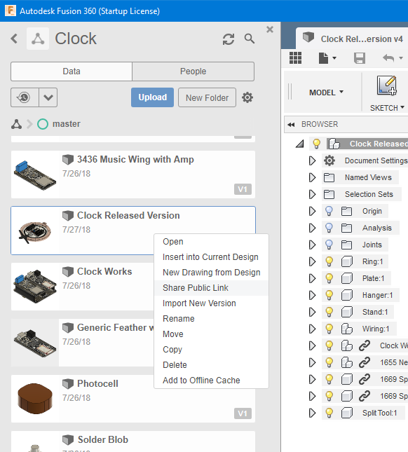
Open up your project and right click on the design and then click on “Share Public Link”.
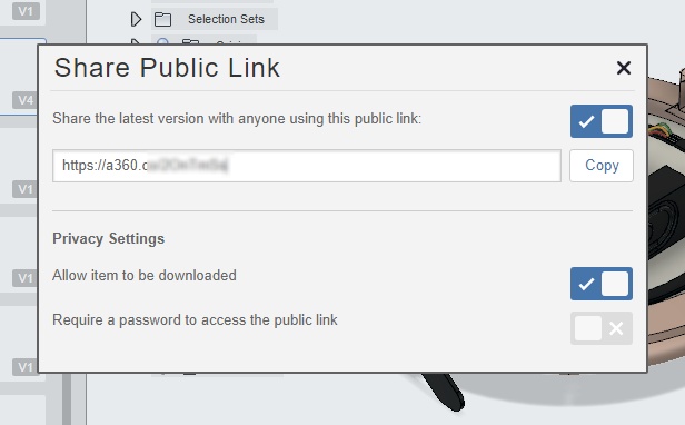
This will bring up a dialog box. You should check “Share the latest version with anyone using this link” and check on “Allow item to be downloaded”. Then copy the link and paste it in your browser.
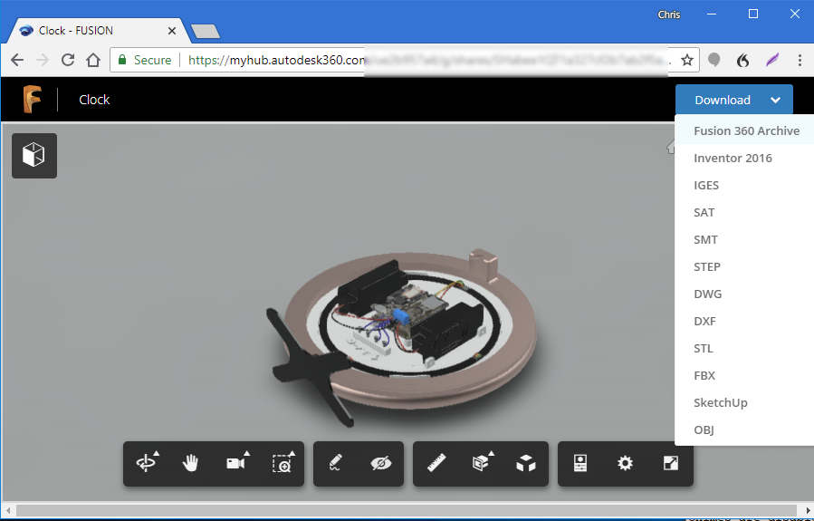
Your design will come up. In the upper right corner click on the “Download” drop-down and select “Fusion 360 Archive”. You will then be prompted to type in an email address and they will email you a link allowing you to actually download the file.
When your email arrives, you will have a link to the file that you can click on and actually download the file. The file format will be in “project.f3z”. Now that you’ve got the file, if someone else needs to open it, it doesn’t just open directly as you might hope. To import one of these files, you need to create a new project.
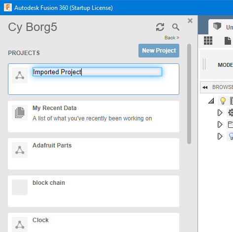
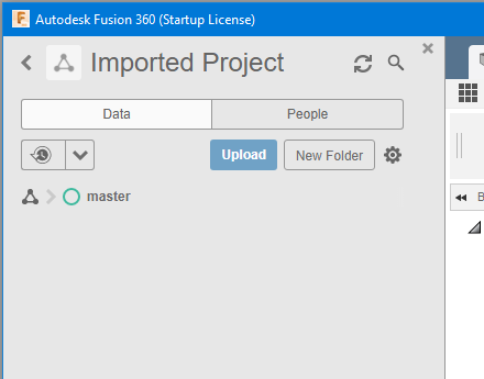
Open the project and at the top of the screen you will see an “Upload” button. It is called upload because all of Fusion 360 files are stored in the cloud under your account.
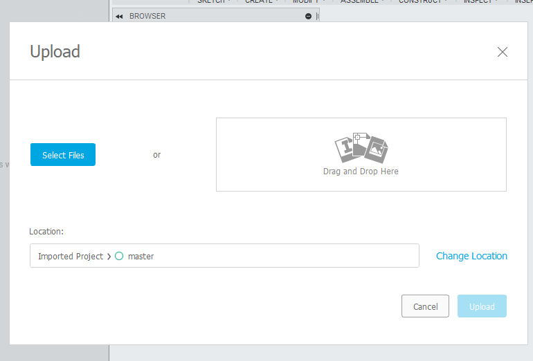
You will then get a pop-up dialog box that allows you to either drag-and-drop the file onto the dialog or browse your hard drive to select your file to upload. After a few minutes the file and all of its linked components will be uploaded and imported into the new project.
Nobody asked me, but it seems ridiculous that Autodesk makes you jump through all of these hoops. They ought to just allow you to do a “Save As” switch to word to your hard drive and have it create the f3z file directly. But at least this does solve the problem until Autodesk gets their act together.
How I Made 3D Printed Customized Christmas Holly Ornaments
My computer rendered Christmas card that I sent to friends and family this year had 3D printing as a theme. You can read all about it here.
Because many friends and family have never seen a 3D printer for the objects it creates, I decided to make a little Christmas to stuff in their Christmas cards. It’s a little piece of Christmas holly customized with their name on it. This video shows how I designed and 3D printing these little trinkets from my friends and family.
3D Printed Icosahedron Star Christmas Ornament
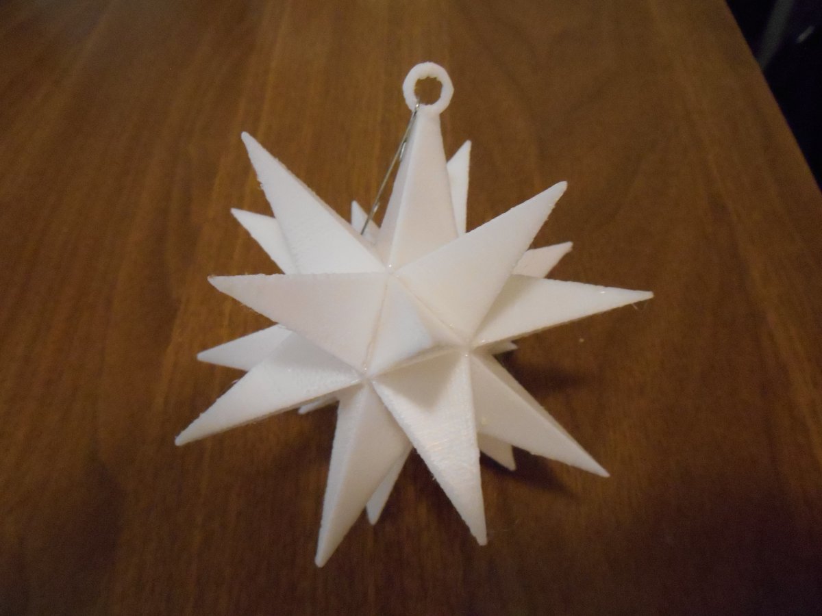
One of the fun things I like to do with my 3D printer is create Christmas ornaments. My radiused is this 20 pointed star shown here on my living room Christmas tree.

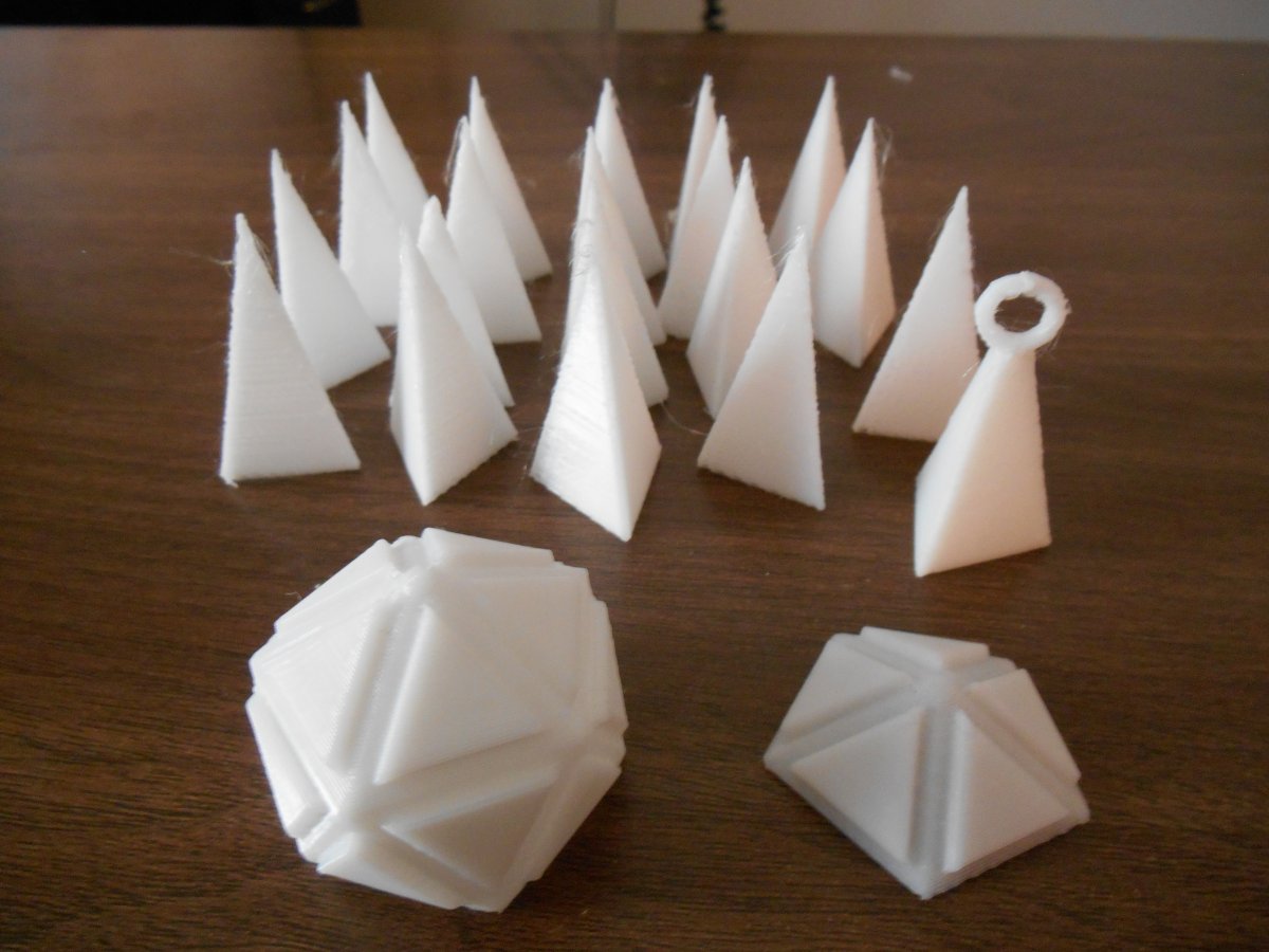
The basic shape begins with a 20 sided shape where each shape is an isosceles triangle. In order for it to print properly I had to cut that shape into two pieces. Then I separately printed the 20 spike shaped pieces to connect to each of the 20 triangles. One of the spikes includes a little loop so that you can hang the ornament.
We used super glue to put the pieces together. After gluing of the spikes onto the two halves of the central core it looks like this.
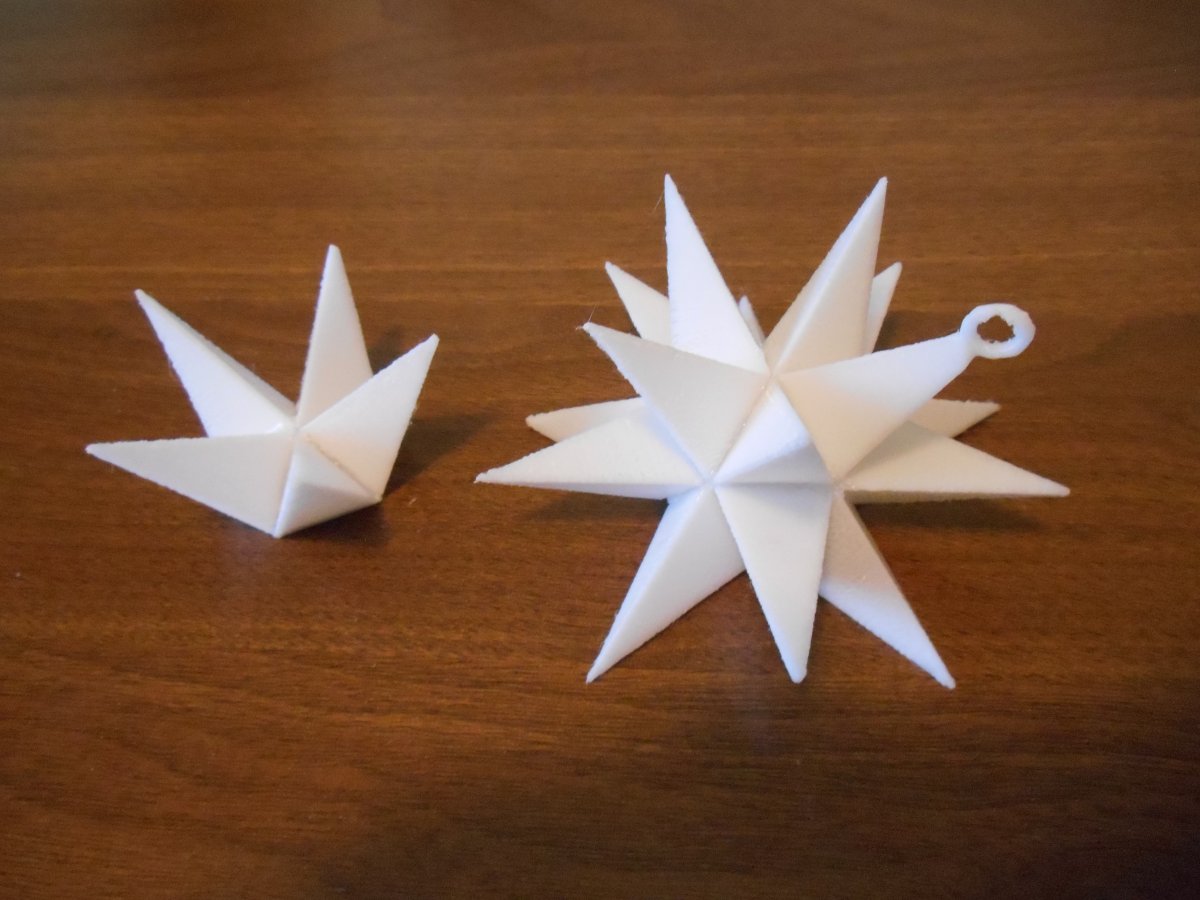
Then we finally glue the two sections together.
The files so you can print your own ornament are available on https://www.thingiverse.com/ by clicking here.
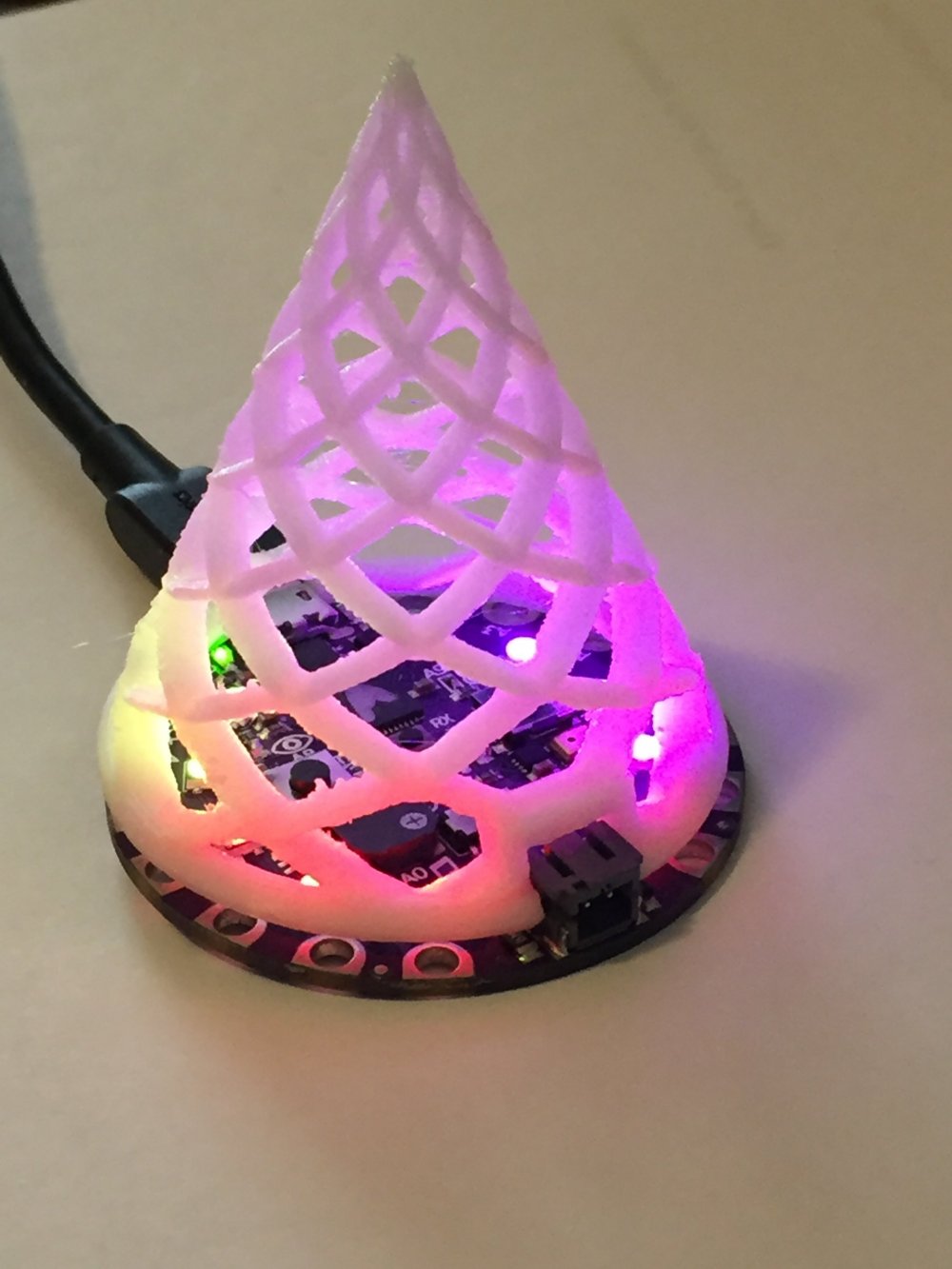
3D Printed Christmas Tree Illuminated by Circuit Playground Express
In 2015 I created some 3D printed Christmas ornaments as seen here. It occurred to me the other day that the tree ornament was just about the right size to sit on top of an Adafruit Circuit Playground Express. The Neopixels would reflect upward onto the ornament. I would have to resize it slightly and cut out some notches for the USB port and JST power connector.
I printed it using white PLA and I think it turned out pretty well. I also have some transparent T-Glaze filament that I may try as well. Here are some photos and a YouTube video showing how it looks.

I will post the code that I used to animate the lights sometime soon. It is currently written in Arduino C++ but I also want to create a Circuit Python version as well before I publish it.
Here is a link to the STL file on Thingiverse.
Here is a link to the original ornaments also on Thingiverse.
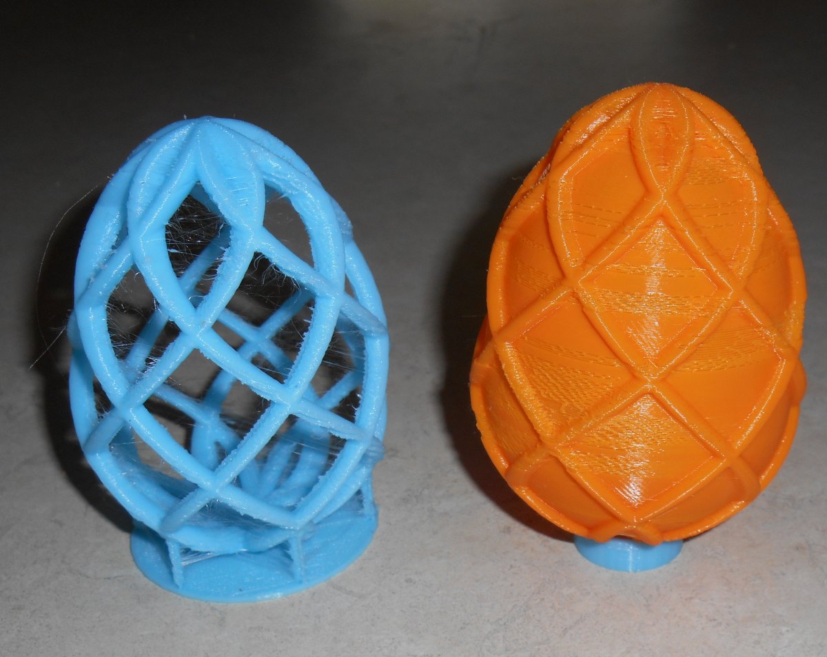
3D Printed Easter Eggs
Last Christmas I made some 3D printed Christmas ornaments so when Easter rolled around this year I decided I would try my hand at designing some 3D printed Easter eggs. Here are the results…
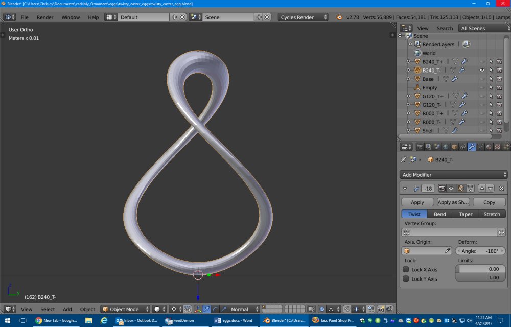
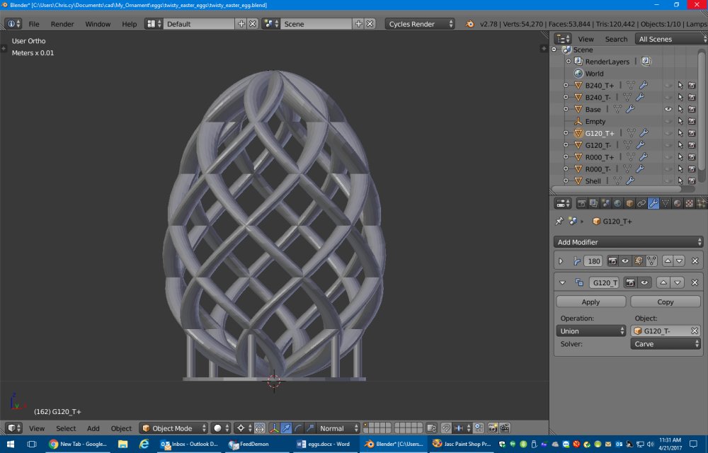
Just like my twisted spear and twisted tree ornaments from Christmas, this one consists of basic shapes given a twist and multiplied at different angles. For the egg I started out with a simple doughnut shape called a torus, selected the top half and scaled that by 1.75 in the vertical to make a basic egg shape.
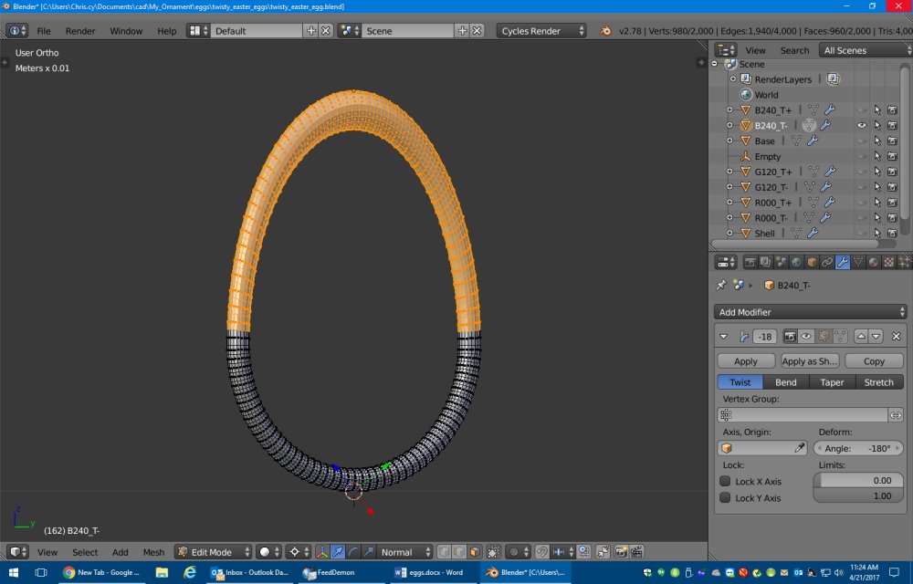 en twisted the shape 180° like this.
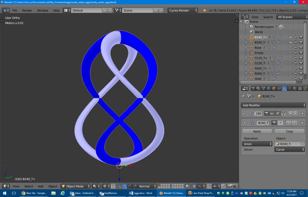
I then made another copy and twisted it 180° the opposite direction. Here I have color-coded each piece light blue and dark so you can see which is which.
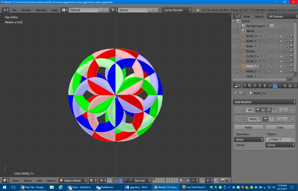
I then made two more copies and rotated them 120° and 240° respectively so that we have a total of six twisted tori. I’ve color-coded all of these as well. There is both a front view at a top view.

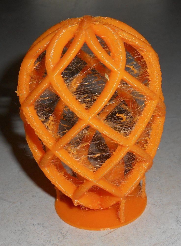
l started wobbling as it printed and I ended up stopping the print because it was just coming out too nasty. I also had lots of problems with threads. Here’s a photo of my first failed print sitting up on a little podium I built.
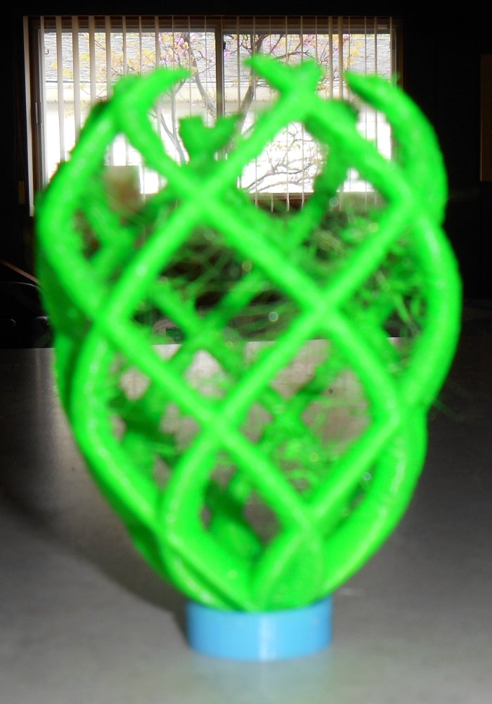
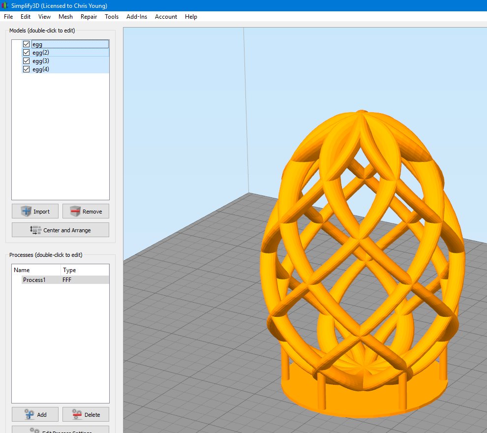
I tried putting supports under it but the automatic support system in Simplify 3D was also creating supports inside the egg which I didn’t want. And I couldn’t get the manually placed supports where I wanted them. I decided to just go back to the CAD program and model supports exactly the way I wanted them and then not use supports in the slicer. I added a base disc and six pillars. These pillars were not necessarily traditional supports to make overhangs print easier. Instead they were just to steady the model while it printed. By the way I was printing with 2 shells and no infill also with 4 top and 4 bottom layers. The base is 1 mm thick. The 6 supports were 2.5 mm in diameter.
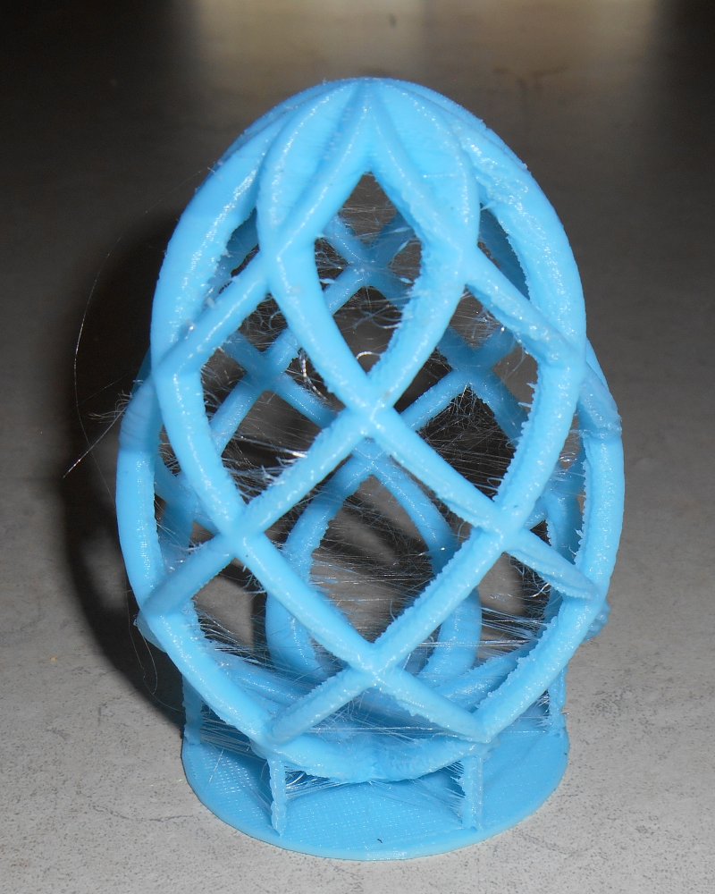
Initially I was still printing with the point down and here is the results.
As you can see I was getting very bad threading. I also didn’t like the look of the model with the pointed end down and that’s when I turned things upside down and put the pointy end at the top to emphasize the egg shape. I also needed to try to reduce the threading somehow to get a cleaner print. I tried increasing the filament retraction and the Z lift but it didn’t help much. I finally decided to turn down the heat from 210°C down to 200°C. I made this change mid-print while printing this blue version. You can see the threading is still bad at the bottom but after I reduced the temperature it was still present but much less so. I didn’t want to experiment further by reducing the temperature so I let it finish at 200°C.
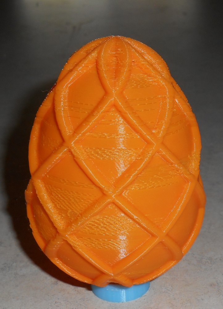
I also tried filling in the gaps in printing a solid shell. Again I started with a sphere shape, selected the top half, and scaled it appropriately. Here is the result.
All of this was modeled in Blender 3D which isn’t really designed to be a modeler for 3D printing. It’s more for rendering and animation but it does allow export to STL format. I’ve been using it because I didn’t want to learn multiple CAD programs and I was under the impression that Autodesk Fusion 360 would only allow you to use it for three years for free and then you had to register it at a very expensive subscription price. I’ve only recently learned that you can continue to renew your free license for enthusiast or student use without having to pay for subscriptions. Only commercial use for companies earning over $100,000 per year requires a paid subscription. I’m not quite sure how you would model this particular object using Fusion 360 but I haven’t had time to play with it yet.
Unfortunately Blender 3D has lots of problems when it comes to Boolean operations on objects or what we used to call in POV-Ray CSG for “constructive solid geometry”. It’s a process of taking multiple pieces and either merging or intersecting them. Although there have been some recent improvements in CSG operations on Blender 3D, it still struggles to merge or union objects that have coincident surfaces. Sometimes you can fudge one object or another by 1/10 of a millimeter and get it to work but it is very finicky.
All of the prints shown here were done without merging the objects. I exported them as a single model with multiple parts. I used an option in Simplify 3D by clicking on “Mesh->Separate Connected Surfaces”.
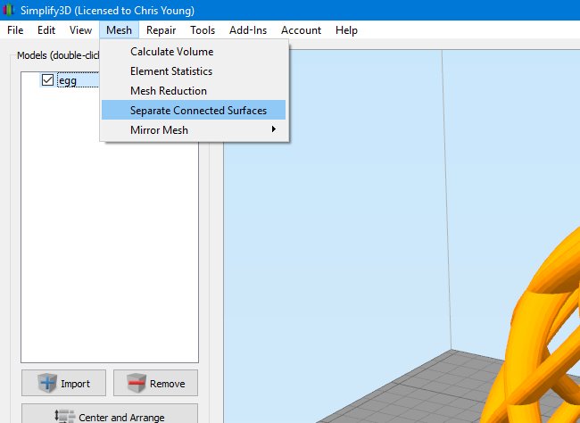
This in effect takes the multiple pieces and merges then in the slicer. There were still some issues with non-manifold parts of the model but I didn’t realize that until after I had printed them. After much tinkering using different options in Blender 3D and fudging the pieces back and forth I was able to get Blender 3D to create a single solid model. Those corrected models are the ones I’ve uploaded to Thingiverse however I have to admit I’ve not actually printed the versions I’ve uploaded. I’m still confident that not only will they print, they should print better than one’s that I actually printed myself.

I demonstrated this project on the Adafruit Show-and-Tell weekly video chat. Click on the icon on the right to see that video.
You can get the original Blender files, some intermediate blender files I used in creating the merged versions, and completed STL files that should print reasonably well. I recommend printing with 2 shells, no infill, and no supports. If you get threading, try turning down your heat. You’re still going to need to do some cleanup on the non-solid version. Threading is always going to be a problem with a print like this.
If you want to export from Blender 3D you can use the file “twisty_easter_egg_merged_2.blend”. If you select the object “Base” it will print the hollow version. If you select the object “Shell” it will print the solid version. The file “twisty_easter_ege.blend” is the original model before I tweaked and merged all the pieces. You can look at it to see how the original design was created.
You can get the files here on Thingiverse. Enjoy!
How I Sleep Better Thanks to My New IPad
I’ve already chronicled the story of my month-long stay in the hospital last December which resulted in getting a trach and being on a ventilator. The worst part of the experience is that I am not be able to talk while on the vent. Fortunately I only need to be on the ventilator now at night to help me sleep. However the communications issues are still a problem. It’s common for me to need to call my dad in the middle of the night to rollover or to suction out the trach.
My main means of communication with my dad while on the vent consists of messages I type on my laptop. My laptop sits on my dresser next to me on top of my cable box. A long HDMI cable runs from the laptop around the back of my bed and up to the TV hanging on the wall over my bed as can be seen in this image.
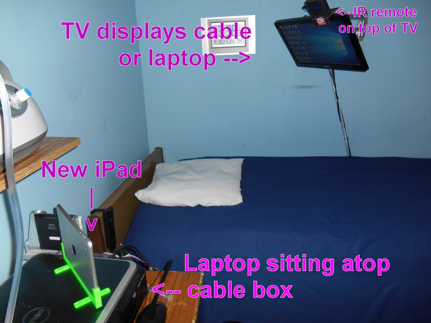
You can click on any of these images for larger versions. There is also an HDMI cable from the TV to the cable box. By switching inputs on the TV, I can either watch cable TV or use the laptop. Normally computer control on my desktop or laptop is via dictation software Dragon NaturallySpeaking but of course if I’m on the ventilator I cannot talk to use the computer. However I have an infrared remote control that not only controls the cable box and TV but it provides mouse control and some keyboard controls for the laptop (mostly arrow keys). The IR control is in the black box sitting on top of the TV.
When I get on the ventilator at about 11 PM each night, I call up a notepad window on the laptop and use the Windows on-screen keyboard. I have it set up in scanning mode and use a single switch on my IR remote to type on the keyboard. I have a couple of files of text with standard messages but then I can type anything I want as well.
The system has worked very well ever since I got out of the hospital late last December but I’m finding it’s uncomfortable to lie on my back all night long. Typically I wake up somewhere between 5 AM and 8 AM and need my vent suctioned. At that point I’m more comfortable if I rollover on my right side.
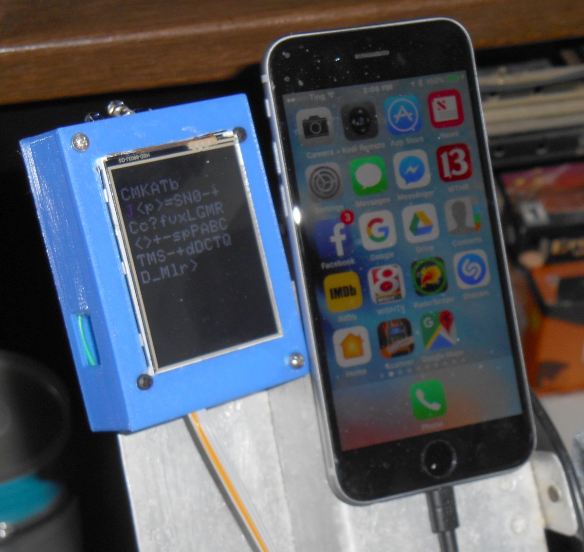
The problem with lying on my side is that I can’t see the TV monitor to see what I’m typing on the laptop. Also there is a small black box on top of the TV that is my IR remote control. It has a 2×16 character LCD display that I need to see in order to operate the IR remote. I cannot see it lying on my side either.
That meant that if I needed to communicate with my dad while on my side we had to play 20 questions. I can signal yes or no with my facial expressions. If that didn’t work he had to take me off the ventilator and insert my talking valve. I needed some sort of device that both he and I could see while lying on my side.
When I was in the hospital I used Bluetooth switch control to type messages on my iPhone to communicate with doctors, nurses, and family. However the iPhone screen is pretty small so I decided I would buy an iPad. I settled on an iPad mini 2. As you can see in the image it sits on top of my laptop and cable box. I could’ve opened the lid on the laptop but it was sitting at an angle that would make it difficult for me to see. The iPad is a better choice. Also if I’m ever in the hospital again I will use it instead of the iPhone because it has a bigger screen.
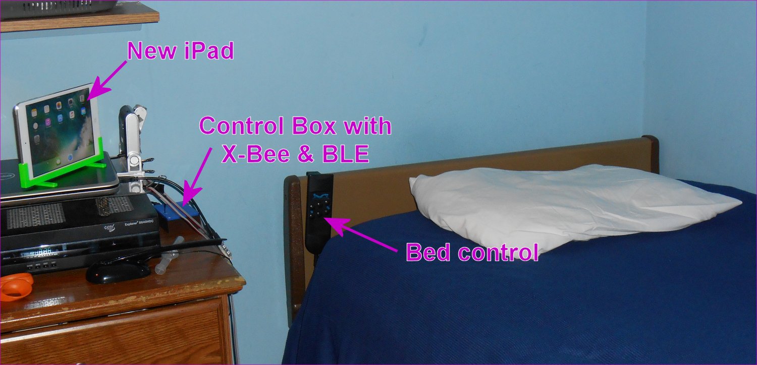
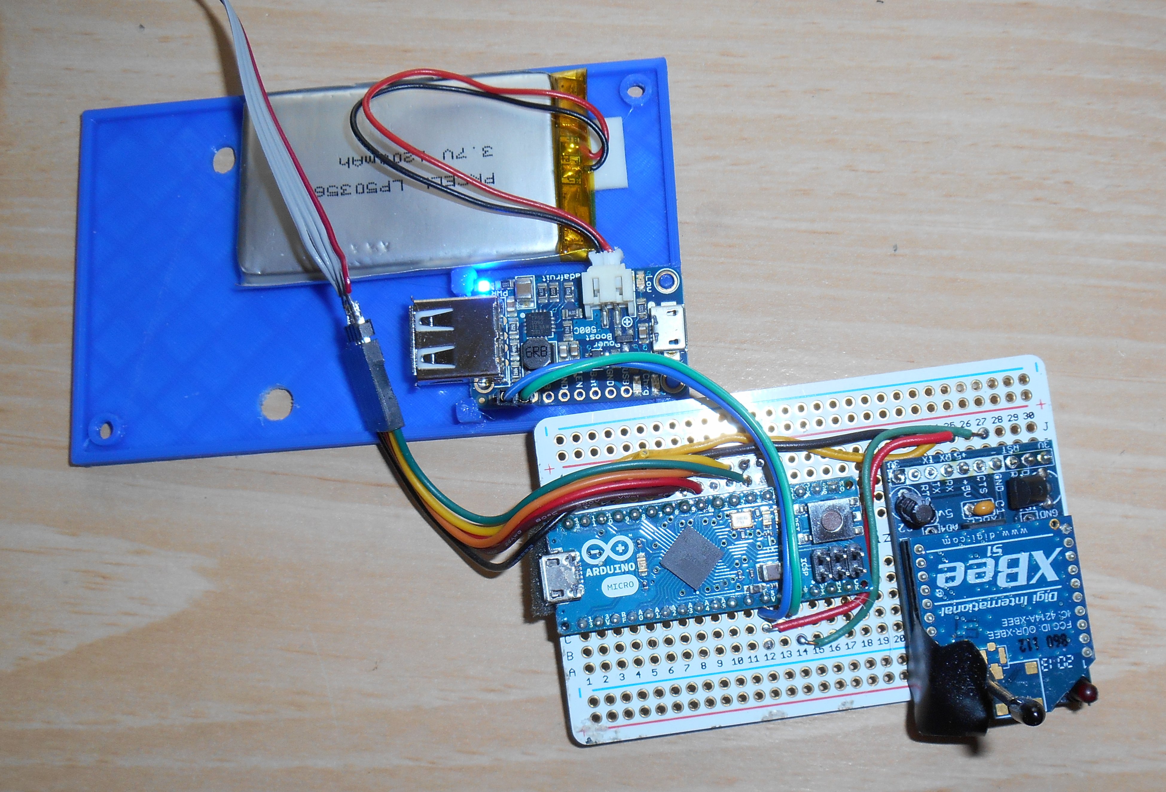
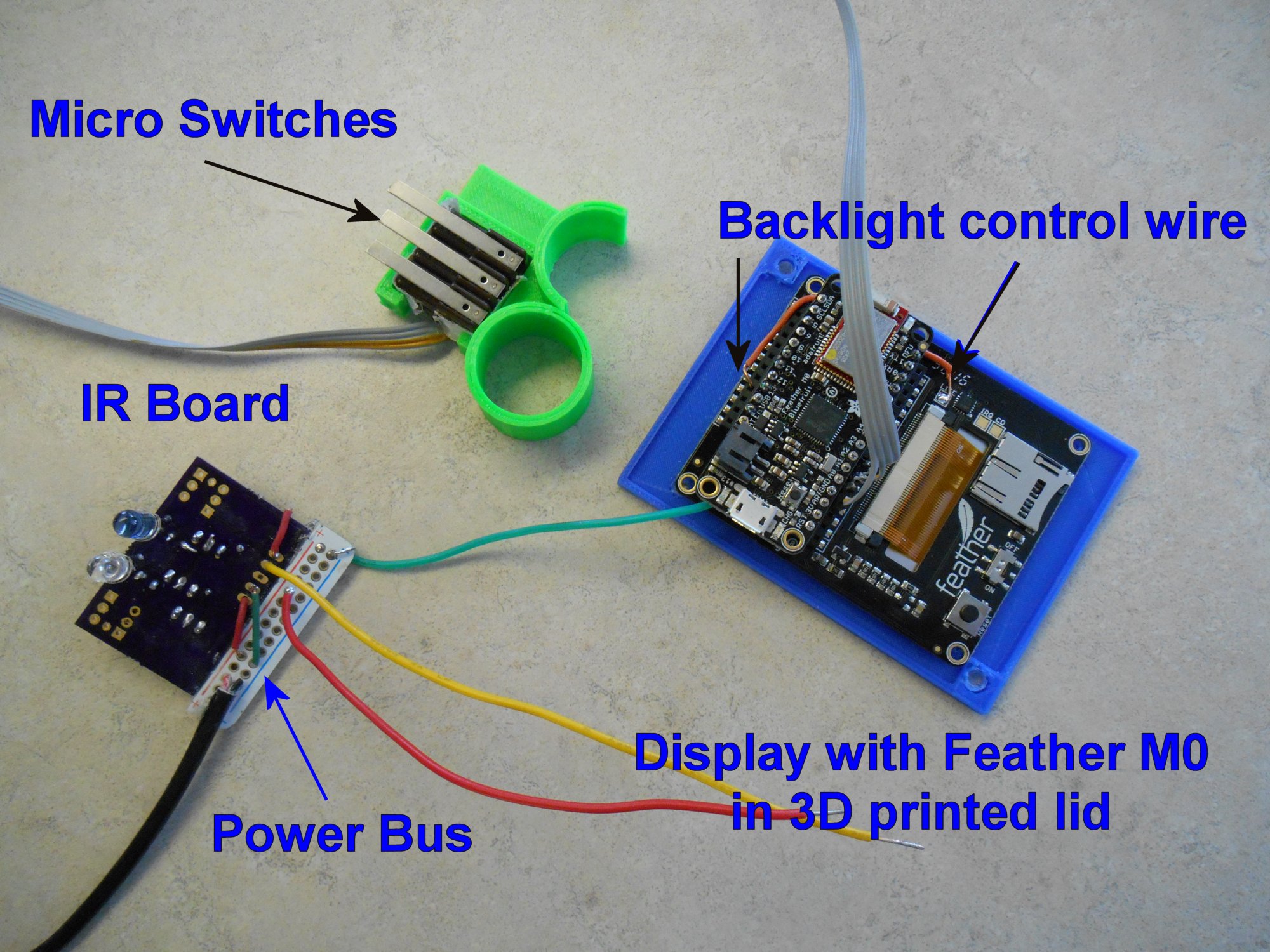
My IR remote sits on top of the TV as shown in the first image above. I control through a control box that sits on the dresser next to the cable box. The two are connected using an X-Bee radio. In addition to sending RF signals to the IR remote, it also sends RF signals to a similar device in my dad’s bedroom so that I can push a certain set of buttons and it sets off the alarm to wake him up to tell him I need something. This image shows the interior of that control box on the dresser. It consists of an Arduino Micro, X-Bee radio, Adafruit Power Boost 500C and a Lipo battery. The battery is a backup in case of a power failure.
Connected to that box are three micro switches mounted in a 3D printed plastic ring that helps me hold the buttons in my hand.
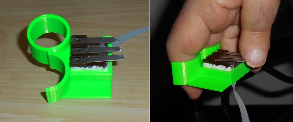
My friend Yahnatan refers to it as my Dr. Strange Sling Ring. It really made me mad when he called it that. I’m not offended. I’m mad that I didn’t think of it first! In order to control the iPad I would need to add Bluetooth of some kind to the X-Bee/Arduino device. I decided to use the Adafruit BLE SPI Friend.
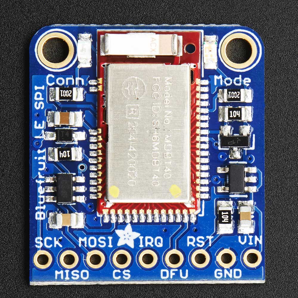 If I was designing the system from scratch I would have used an Adafruit Feather 32u4 BLE with one of their RF feather wings but those didn’t exist when I first built this project. I’ve got everything already designed around a 5 V device and the X-Bee RF system. I also didn’t plan ahead thinking that I would someday need to attach an SPI device like the BLE Friend. Unfortunately I had already used the dedicated SPI pins on the Arduino Micro for other purposes. Fortunately the Adafruit Bluefruit software library has an option for software SPI. It will allow me to use any set of six pins to connect the device. I was pleasantly surprised that that feature worked right out of the box.
I have the software configured so that if you press all three buttons simultaneously for more than one second it toggles between IR mode and Bluetooth mode.
The only remaining task was to make a 3D printed stand for the iPad. I wanted something that would hold it perfectly straight up and down 90°. It had to be stabl enough that it wouldn’t knock over to easily but I wanted to be able to fold it up so it would lie flat for transport when not in use. Should I ever end up in the hospital again I would be using this iPad rather than the iPhone to communicate with doctors and nurses.
The photos below show my 3D printed stand. The legs are not solidly printed on the long beam. They are attached with 4-40 machine screws so that they can pivot 90°.
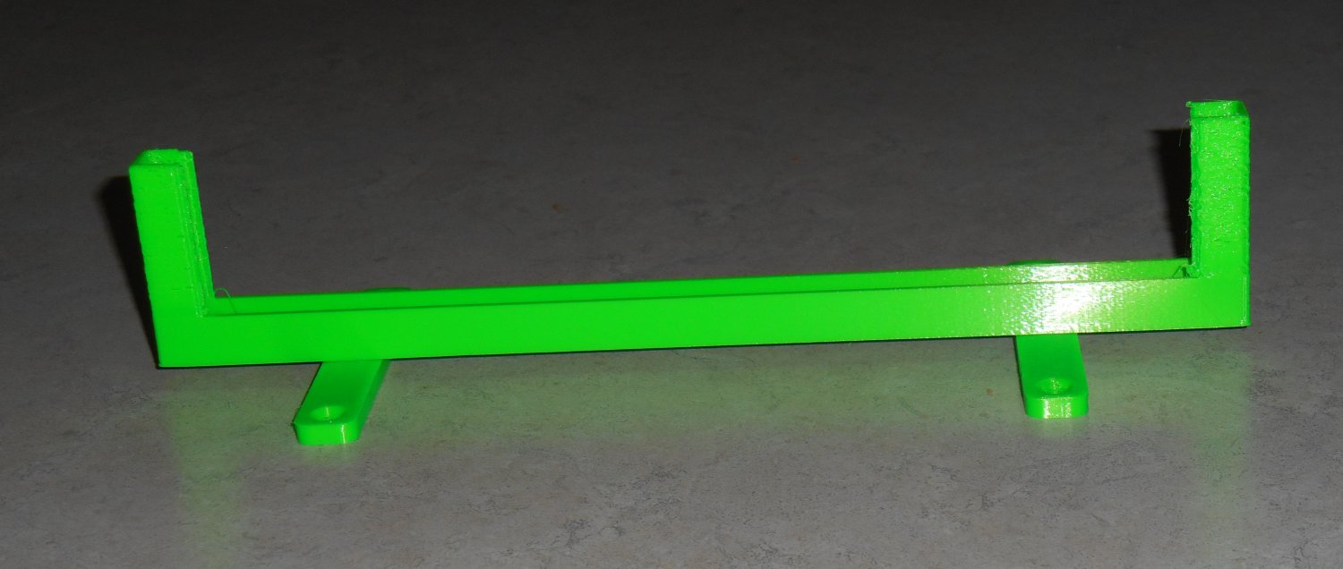
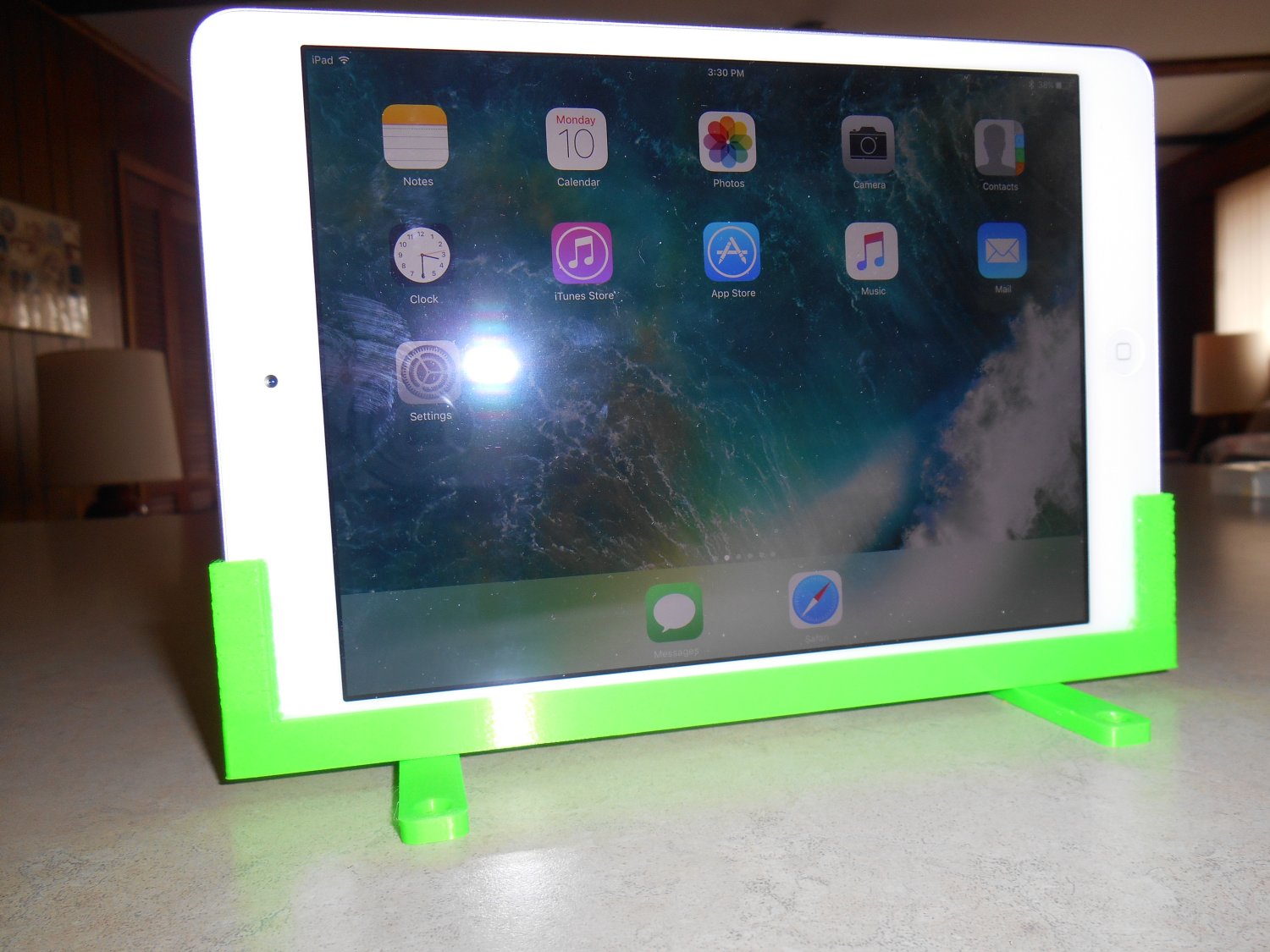
I’m still a little bit concerned that it may be unstable. I tried to make 3D printed suction cups using Ninja Flex however the rim of the cups was not smooth enough to make an airtight seal. I ended up buying some suction cups from Amazon but they have not arrived yet. I’m not sure if I’m going to install them or not.
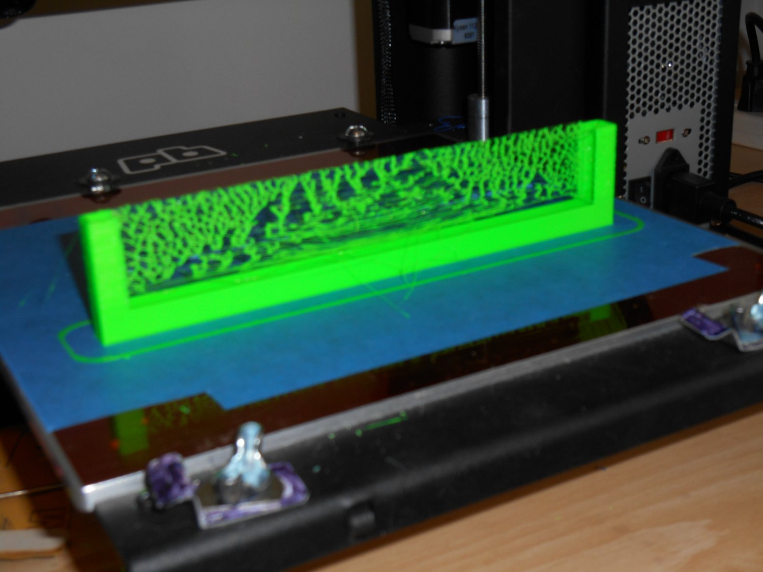
One other item to share… I must’ve been using some really cheap PLA plastic that was very stringy because as the stand was being printed there was an unusual amount of threads connecting the two uprights. The end result looked like some sort of weird tennis net. I’ve never seen threading this bad. Of course it was easily broken off and removed but I thought it was so bizarre I had to share it.
I been using the device for a couple of weeks now and it works really well. It allows me to not hesitate to roll over on my side where I can sleep more comfortably and know that if I need to communicate with my dad I can do so easily.
I talked about this project on the weekly Adafruit Show-And-Tell video chat. You can see that video by clicking on the icon on the right.
The Ultimate Remote is Dead. Long Live the Ultimate Remote 2.0
In late 2015 I built a piece of assistive technology that I called my Ultimate Remote. The device was an infrared remote for controlling my TV and cable box. It also had infrared mouse control for my computers. There were also limited keyboard commands mostly arrow keys, enter key, backspace and some control keys for doing cut-and-paste. Finally it was a Bluetooth device for doing accessibility switch control on my iPhone. I wrote about it in this blog post from January 2016.
The core of it was an Adafruit Micro BLE device which was discontinued shortly after I purchased it. Adafruit replaced it with the Adafruit Feather 32u4 BLE. The Micro BLE also had an ATMega32u4 which is one of my favorite 8-bit processors.
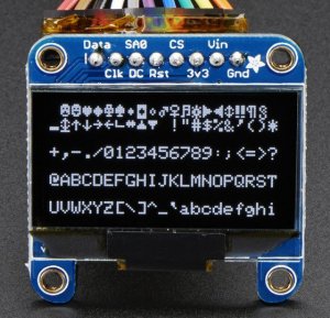
The display was a monochrome 1.3 inch 128×64 OLED graphic display. It also contained one of my infrared I/O boards although it only did output. I didn’t really need to read any IR codes. On the end of a long wire were three lever micro switches that I would hold in my right hand to control the device.
The device served me well for well over a year. It was critical to me during my recent hospital stay where I was on a ventilator and could not talk. I used the switch control to type notepad messages on my iPhone and communicate with the nurses and doctors. You can read about that adventure here.
The micro switches have always been the weakest link in my devices. I have to use switches that have a feather touch to them and that means they are very fragile. The switches get knocked around quite a bit and so it was inevitable that one of them would break. About a week ago one of the switches failed and we had to replace them.
I had planned for many months to rebuild the entire device. I had used up all of the program memory in the device and could not add any new features or any new IR commands. I did not have codes installed for my Blu-ray player and there wasn’t any room left. In fact one time I had tried to recompile the code and because one of the included libraries had been updated, the code wouldn’t fit anymore. I don’t know if it was the Bluetooth BLE library or the graphics display library but something changed. I had to go through my code and try to free up some space by eliminating some error messages or shortening other messages. I finally got it to recompile but the writing was on the wall that I needed to upgrade.
The obvious choice was to use a new Adafruit Feather M0 BLE. Instead of the traditional 8-bit 32u4 running at 16 MHz with 32K flash memory and 2.5K RAM, I would have a 32-bit ARM Cortex M0+ running at 48 MHz, with 256K flash memory and 32K of RAM. The main problem was that my infrared library IRLib did not support these newer 32-bit ARM processors.

I had just recently spent weeks researching the new processor and converting my infrared library to support the newer chips. The timing and frequency modulation portions of my IR code are extremely dependent on the internal timers of the processor and that is very hardware dependent. I had to learn a whole new system of timers and PWM frequency control to rewrite the code. Fortunately I got it running just in time.
Although I had the infrared code working on the new processor, and had a Feather M0 BLE available to build a new device, it should not have been necessary to rush the new device into construction. All we had to do was repair the old remote by replacing the micro switches. I already had another set of switches assembled in anticipation of building the new remote. All we had to do was cut the cable on the old one, splice in the new cable and everything would be fine.
Dad decided that rather than having a stiff, unsightly splice in the middle of my cable, he would open up the box, unsolder the old cable and solder on the new cable. He ended up completely disassembling everything to get at the wires that needed replacing. I appreciated that he would go to that trouble even though this device was going to get replaced probably in a month or two. Unfortunately this was a bad decision.
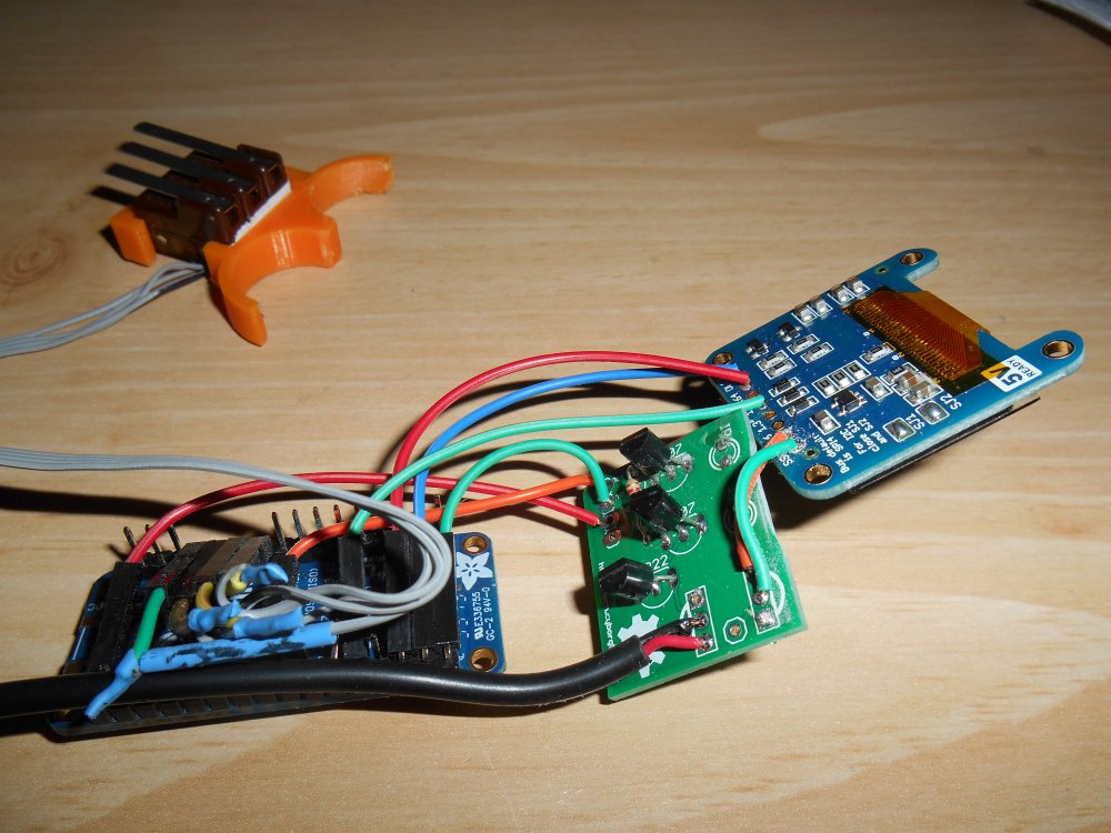

Above are photos of the interior of my original ultimate remote. As you can see the wiring is pretty complicated. Unfortunately I only have about four different colors of wires available so we had to use the same color wires for different purposes. For example there are multiple green wires used for different purposes. After replacing the cable to the micro switches, dad tried to plug everything back in the way it was. We plugged in the device and I tried pushing the buttons but nothing would happen. In the course of trying to figure out what was wrong he touched one of the infrared LEDs and discovered that it was very nearly becoming more red than infra. It was too hot to touch. Although we did not get a visit from the infamous “Blue Smoke Monster”, if we had left it connected very long we would’ve had at least smoke and possibly fire as well.
It didn’t take us long to find out that the culprit was 2 green wires that had been crossed. We fixed the wiring and plugged it back in. No heat this time. The device worked intermittently for about five minutes and then quit working altogether. It was obvious that we had burned out the IR LED at least and possibly the transistors driving them.
Fortunately I had sufficient parts to build a new IR output board so we spent the next afternoon building it and installing it. It would not work either! One of the problems we were facing was that we had assembled and disassembled the box many times. I had been using small gauge stranded wire with silicone insulation. That is very flexible and made it easy to route the wires in a tiny box. However several of these wires were soldered into through hole locations on the circuit boards. Right at the point where they are soldered in, they are extremely susceptible to breaking if they are bent back and forth too many times. A better solution would have been to put a header pin in the hole. Then we could solder the stranded wire onto the pin and cover it with a piece of heat shrink tubing. At this point it was too late to do that.
We tried repeatedly to diagnose the problem with the new IR board but every time we fixed one thing, something else would break. There was also the possibility that we had damaged the Adafruit Micro BLE board itself. As I mentioned earlier, that board has been discontinued so there was no possibility of replacing it. After two full afternoons of working on it, I decided to throw in the towel and put all of our efforts into building the completely new device that had been planning for months.
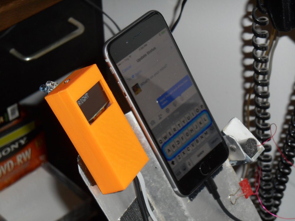
I had all of the necessary parts. The new device would have a much larger 2.4 inch TFT color graphics display instead of the 1.3 inch monochrome OLED. This device also features a resistive touchscreen however I don’t have any use for that feature. It also includes a slot for an SD memory card. I may come up with a future use for that.
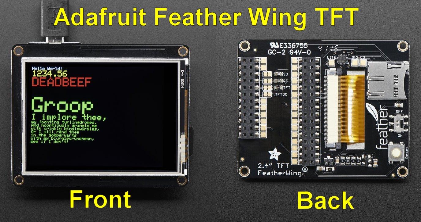
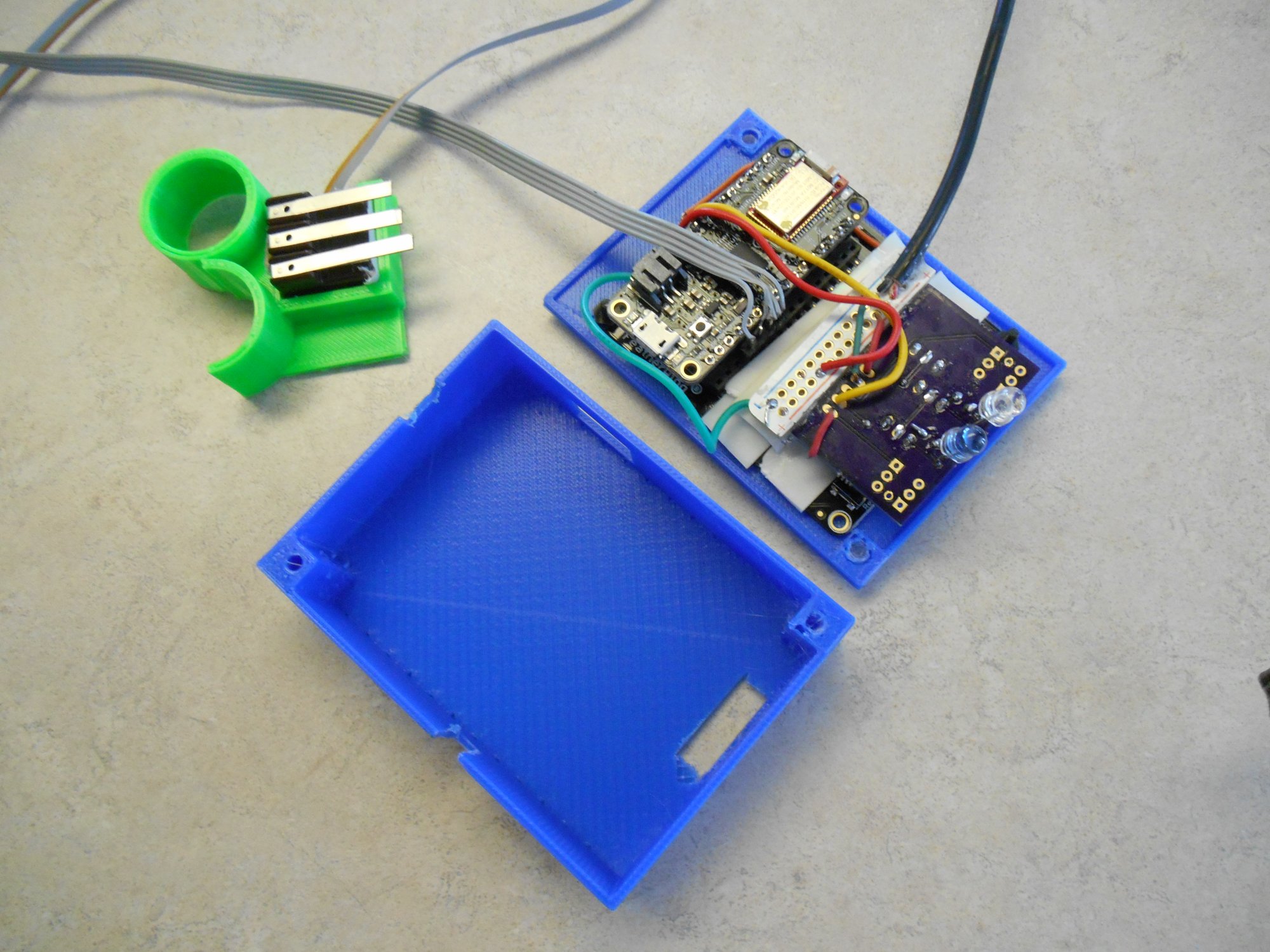
One of the nice things about the Feather Wing TFT board is that the feather board plugs into a socket in the backside. You don’t have to run wires from the main processor to the display board. However one of the disadvantages is that there is only one power and one ground pin on the device. So I was going to have to cut up a little piece of prototype board to make a power and a ground bus. This would bring in power from the outside, connected to the Feather and display boards, and run power to the infrared board. Similarly I needed ground wires to all of those parts plus a ground wire for the micro switches. We also needed to solder a jumper so that I can turn the backlight of the display off and on. There is a solder pad available but you have to jumper it to one of your Feather pins.
Although the Feather boards have a built-in battery connector and a battery charging circuit, I decided to power the device from an external 5v battery source. My old Ultimate Remote was a 5v device throughout while the Feather system runs on 3.3v. In the old system I had a short cable with a barrel jack running from the remote into a battery pack I call a Printy Boost. The Printy Boost is a device which I designed for the Adafruit Learning System as seen here. The Printy Boost also provides extended battery life to power my iPhone. So rather than have a separate battery for the remote and for the iPhone backup power I decided I would stick with the old system and run a cable from the Printy Boost into the remote just like I did before. Rather than connect to the +3.3v pin I connected to me “USB” pin which was the same as powering it through the USB cable at 5v.
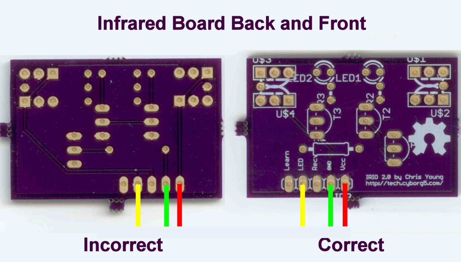
There are some differences between the Feather TFT board and the old monochrome OLED graphics board so I had to tinker with the software to get things to run. Most of it was compatible because Most of the Boards operate on the Adafruit Graphics library but there are still differences. Once I had display software converted I tried using the device. Unfortunately it didn’t work again! You would think I would be more careful about crossed wires after the previous fiasco. It turns out we had the infrared I/O board wired backwards. I had drawn the wiring diagram looking at the front side of the IR board. That means on the right 2 pins are power and ground. Then moving to the left you skip one pin and the next one is the IR output. However the way the board is oriented in the device, the backside of the board is facing upwards. We wired it with power and ground on the right but that was wrong. Fortunately this just meant that the power lines were going to the receiver pins which were not being used in this application. So nothing burned out. We reversed the wiring and everything worked fine.
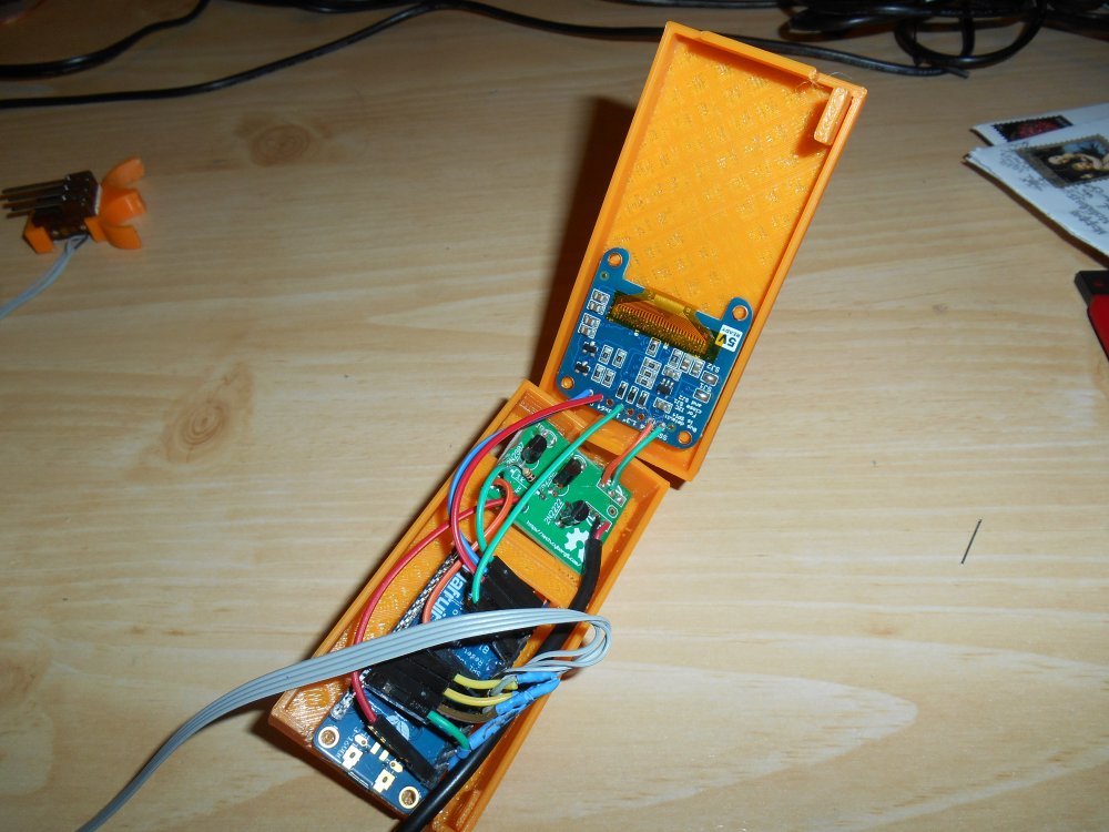
The final step was to design a 3D printed enclosure for the device. That took another afternoon or so.
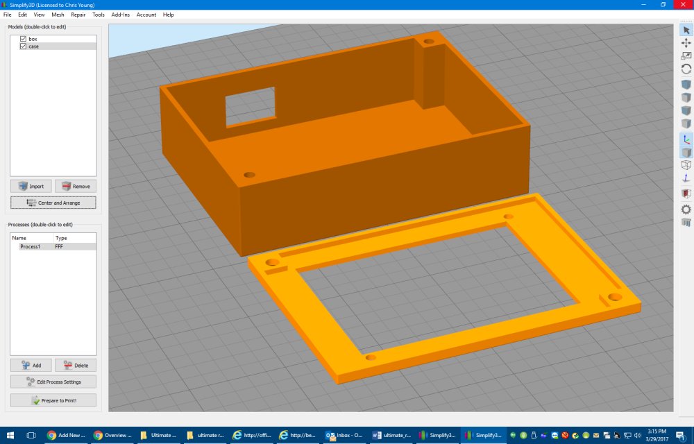
We mounted the TFT display into the lid of the box using black nylon plastic screws and nuts out of this kit sold by Adafruit. They are really handy because they are selected to fit in the 0.1 inches diameter mounting holes used in most Adafruit boards. When that box of screws was first added to the Adafruit catalog I knew I would need them someday and purchased it right away. They work perfectly so it was a great purchase.

The rest of the box is held together by 5/8 inch sheet metal screws. I like using sheet metal screws because they have a pointy end that taps really well into 3D printed PLA plastic. Here are some more photos of the completed project.
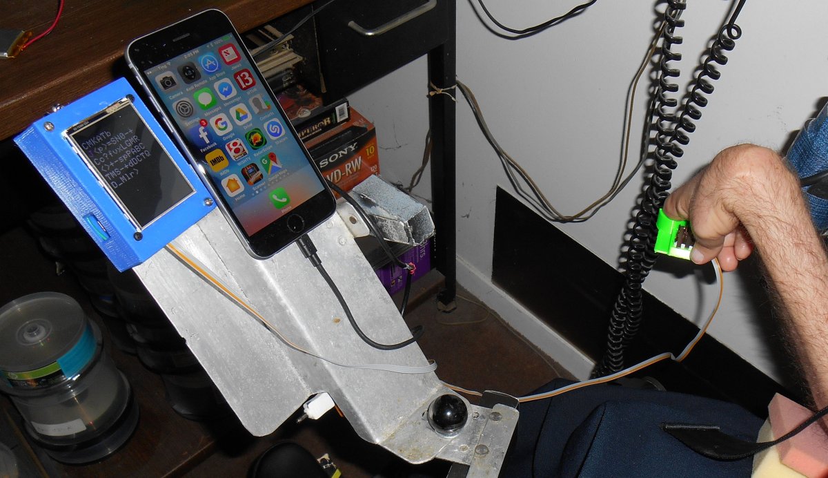
There are still lots of software tweaks I have to implement. It takes longer to erase a 320×240 color display than it does to erase a 128×64 monochrome display. The monochrome device required you to call a “display” method to update the display after writing to it. The new color device updates as you write to it. The result is you can see the screen update where the old one would update instantly. I think the updates actually slow down the entire process a little bit. So I’m going to have to optimize the code so that it only updates the screen when absolutely necessary and only does it in small pieces. In the old system it was easy to just erase everything and redraw it from scratch every time but that won’t work very well in the new system.
Of course I also have to add all the features I’ve been wanting to add but didn’t have sufficient memory under the old system. I have to add all the codes for my Blu-ray player and there are some additional keyboard codes that I want to add. I may end up implementing an entire keyboard system so that I can type anything using IR codes. I’ve developed a special protocol for my IR library that allows me to use any mouse or keyboard commands possible. I’ve only been using a fraction of that capability.
One other difference between the old and new system involves the power output of the IR board. When I originally designed my infrared I/O board I ran the LEDs with no current limiting resistors. Because the LEDs are only intermittently running (assuming you don’t cross your wires), it’s safe to put more than 1 amp through them. But my experience is that sometimes USB power can’t supply enough power when that current spikes during transmission. So I’ve added some 33 ohms current limiting resistors in line with the LEDs on the latest version of my infrared I/O board. The old device did not have these resistors but it ran well because it was powered by a battery pack rather than a USB plug. Now that I’ve worked with the new remote I’m realizing it doesn’t have the power of the old one. I’m going to try shorting across those resistors and see if it helps.
I still have fond memories of my original Ultimate Remote. It served me well for over a year and was literarily a lifesaver while I was in the hospital. But I’m also looking forward to the new things I will be able to do with the new improved Ultimate Remote 2.0.
Afterward: After I completed the project I presented it on the weekly Adafruit Show-and-Tell. I was the first guest in the video below.
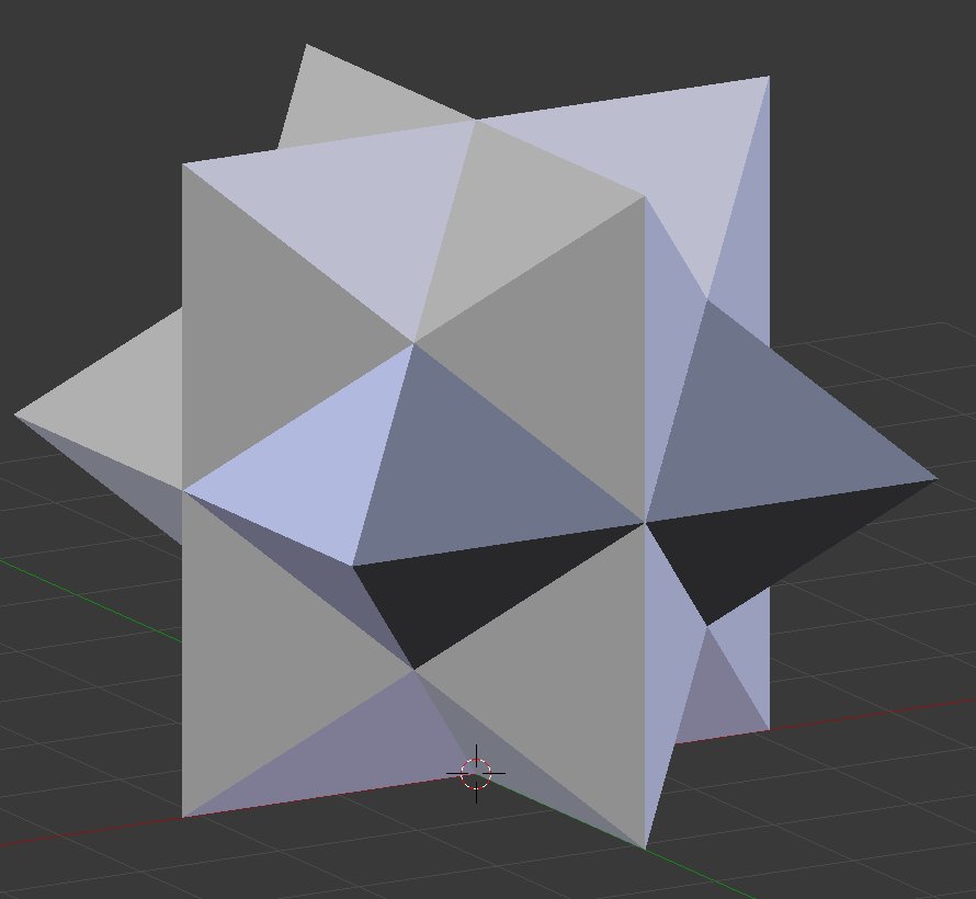
3D Printed 6 Piece Star Puzzle
When I was a child I used to enjoy playing with little puzzles. One of my favorites was a 6 piece star-shaped cube that I thought was particularly clever in its design. I decided I would try to 3D print one of those puzzles. Before going to the trouble of designing it myself I decided I would look on Thingiverse to see if someone had already created it.

This particular puzzle was available in several versions including this one on the right.
However it wasn’t exactly like the one I remembered. All of them that I found on Thingiverse had six identical pieces. I also saw some YouTube videos on how to assemble such a puzzle. It looked to me like it did not stick together very well.
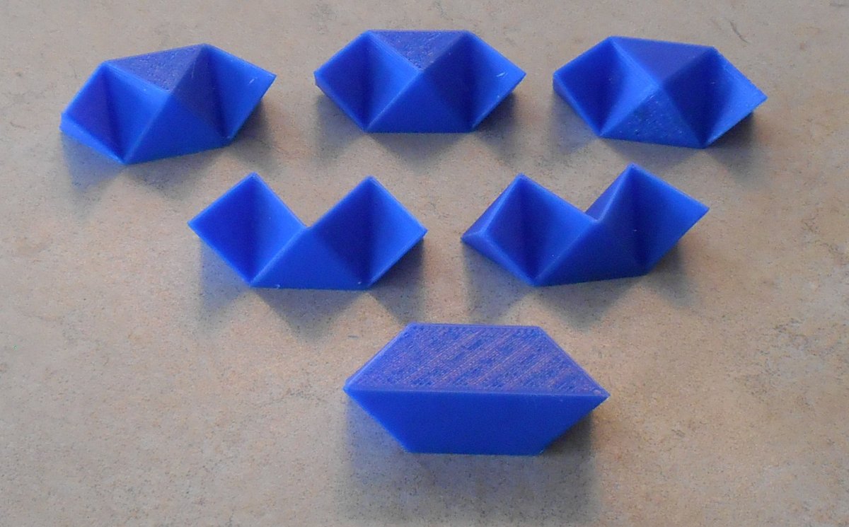
The puzzle that I remembered also had 6 pieces but they were of three different types. Three of the pieces were identical to the ones in the Thingiverse models. Two of them were similar but they had a notch cut out. The final piece was completely solid and would be slid into place to lock everything together at the end.
So I made a modified version of the model linked above. I had to do a little tweaking to get the tolerances right but it turned out okay.
You can download my modified puzzle on Thingiverse at https://www.thingiverse.com/thing:2160633
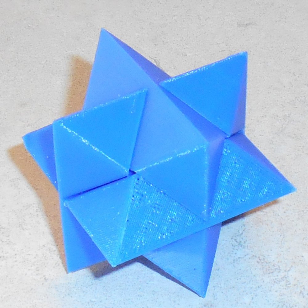
Here is a photo of my completed puzzle.
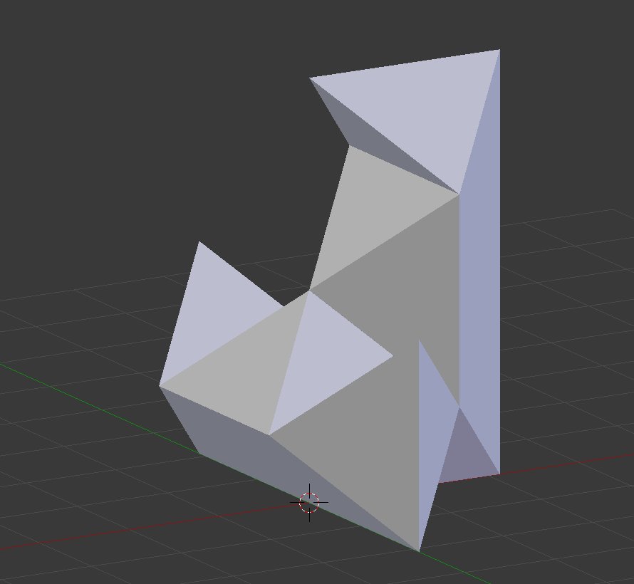
Here is a photo of the individual pieces. I refer to the pieces as “part 1”, “part 2” and “part 3”. That designates how many of each of the pieces there are. That means there are three copies of “part 3” and so on.
Here is how to assemble the pieces. Start with a piece 3 in this orientation.
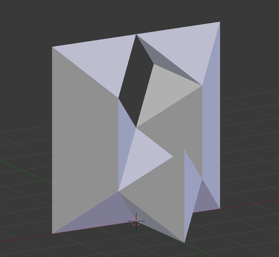
Add another piece 3 vertically on the right side.
Add the final piece 3 vertically on the left side.
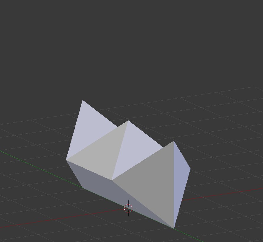
Place a piece 2 horizontally across the back with the notch on top.
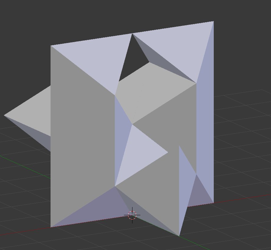
Place the other piece 2 horizontally across the front with the notch on top.
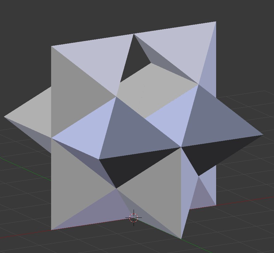
Slide the final piece into place from the front in a hole left by the notches.
Many thanks to by HotIceT for the original design. My piece 3 is identical to his and the other pieces were derived from that by modifying the STL files in Blender 3D.
Modifying the “Pause at Height” Cura Plugin for Printrbot Plus
Recently I did some 3D printing objects as a kind of diorama that I photographed for my 2016 Christmas card. One of the objects was this sign saying “Emmanuel – God Is with Us”. The background or base of the object was printed in brown filament and the raised lettering was printed in white filament. I use a single extruder Printrbot Metal Plus.

The trick to printing this is to print the brown portion, get the printer to pause while you change filaments, and then print the white lettering raised above it. I’m using Cura 15.04 which is the most recent version that can be easily configured for Printrbot. It has a plugin called “Pause at Height” that is designed to allow you to do just what I want. You pick a Z height at which the printhead is retracted and paused while you swap the filaments.
If you open Cura and click on the “Plugins” tab you will see the following:

There are two plugins installed by default. The one we are interested in is Pause at Height. You click on the plugin and then click on the tiny down arrow at the bottom of the window and a dialog will appear that allows you to set the parameters for the plugin. It will look like this…
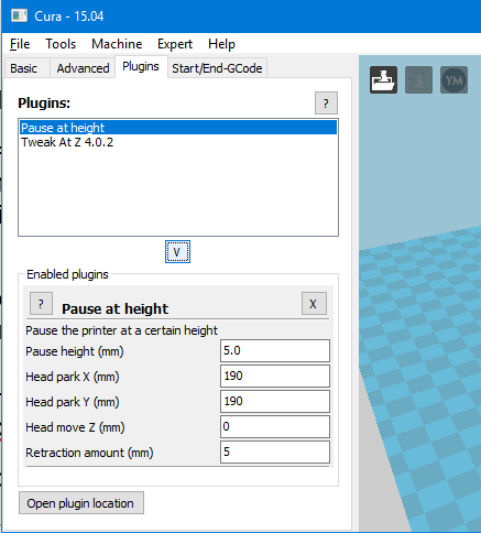
It gives you a series of parameters that you can fill out. Then when you print your object, theoretically the printer will pause and allow you to change filaments. Unfortunately the Printrbot Metal Plus does not have any sort of control panel so there’s no way to resume the print once you’ve paused. I tried using the plugin anyway just to see what would happen. At the proper point in the print, the printhead retracts back and to the side as it’s supposed to. But rather than pausing, it immediately goes back where it left off and begins printing.
If you look at the lower left corner of the plugin screen you will see a button that says “Open plugin location”. If you click on that button here’s what the folder looks like in Windows Explorer.
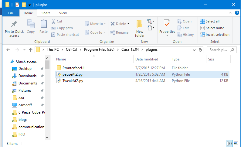
You can see the plugins are actually Python programs that have a .py extension. We want to look at the one named “pauseAtZ.py”. We will open it up in our favorite text editor and take a look around. If you look at the code at approximately line 104 you will see this
#Move the head away
f.write("G1 X%f Y%f F9000\n" % (parkX, parkY))

#Disable the E steppers
f.write("M84 E0\n")
#Wait till the user continues printing
f.write("M0\n")
#Push the filament back, and retract again, the properly primes the nozzle when changing filament.
f.write("G1 E%f F6000\n" % (retractAmount))
f.write("G1 E-%f F6000\n" % (retractAmount))
It appears that this Python script is reading and writing your G-code looking for the proper place to do the pause. Then it inserts additional G-code to do the retraction and the actual pause. The important line is line number 110 which inserts the G-code command “M0”. This is a stop command as described here
http://www.reprap.org/wiki/G-code#M0:_Stop_or_Unconditional_stop
Apparently the firmware in the Printrbot Metal Plus does not recognize that particular G-code. There are other G-code options that we can substitute.
Using your text editor, do a “save as” and give it a different filename with a .py extension and save it in the same folder as the original. Modify line number 110 to read as follows
f.write("G4 S30\n")
The “G4” command is described here
http://www.reprap.org/wiki/G-code#G4:_Dwell
It causes a 30 second pause. I found that this gives me sufficient time to withdraw the original filament, replace it with a different color, and force some of the new filament through the nozzle to flush out the old color.
There is one other change you should make in that file. On the very first line it reads:
#Name: Pause at height
This is the name that appears in the plugin tab of Cura. You should change this name to something like
#Name: My Modified Pause
so that you can distinguish it from the original plugin.
I made those changes, selected the modified plugin and it worked perfectly. You have to play around with the preview slicing to determine what level you need to set for the pause. You might try printing a small test piece if your object is extremely large.