I did not create this. I found it on YouTube but it is worth checking out.
Category Archives: Uncategorized
Information Technology to Rescue Census Again
A recent article on the technology blog Engadget reports that the 2020 census will probably take greater advantage of the Internet rather than mailing out census forms printed on paper. The article says it’s only natural since so much of the rest of our world is forgoing “snail mail” and going to Internet-based data collection. The article says that the 2010 census cost $95 per household to process. The cost savings of using Internet should be substantial.
However this is not the first time that information technology has come to the rescue of the US Census Bureau. The census is a vital part of our government because census data is used to draw congressional districts and to allocate federal funds to various areas based on population in addition to all the other useful information it provides for city and state planners and policymakers at all levels of government.
When the country was going at a huge rate in the late 1800s the census was also vital because the population was shifting so rapidly with tens of thousands of immigrants coming in all the time and people moving to different parts of the country as we expanded westward. However the task of taking the census and tabulating the data by hand was overwhelming. It took a full eight years to tabulate the 1880 census and estimates were that the 1890 census could take as long as 11 years to tabulate. Of course by then we would already be a year overdue for the 1900 census.
The census however was rescued by Herman Hollerith. He worked for the Census Bureau and came up with an idea of using pieces of cardboard with holes punched in strategic locations to represent data. He’d gotten the idea by seeing a device called a jacquard loom. The jacquard loom would weave intricate patterns of lace and other woven materials by using a set of punched cards. Metal pins would either drop into the holes or be blocked by the absence of a hole to determine which threads should be raised or lowered as the material was woven. He concluded that we could punch holes in cards to represent different bits of data and that a machine could be built to tabulate those results electronically. Metal contacts would either drop through the holes or be blocked by the absence of a hole in it would trigger an electric counter. He designed the cards to be the size of dollar bills at that time since there were already pieces of equipment available to handle slips of paper that size.
The end result was a tabulating machine that was used in the 1890 census to tabulate it in just one year instead of the predicted 11 years. He formed a company known as the “Tabulating Machine Company” which later merged with other firms to form the “Computing Tabulating Recording Company“. That company was later renamed in 1927 to be called “International Business Machines” more commonly known by the initials IBM.
Click on the name Herman Hollerith to read the Wikipedia article giving more details about the man and his inventions and how he revolutionized data collection by using the infamous punched cards. You don’t see punched cards anymore these days but in its day, it was information technology that rescued the census.
Electronics Pun
Once upon a time there was an evil dictator of a small country. Rebel forces within the country fought for freedom of the people and repeatedly attempted to overthrow him. When he would find a village that was harboring the resistance fighters he would routinely cut off the electrical service to the village. However when that would happen, cargo planes would mysteriously appear over the villages and drop supplies to them. The parachute dropped crates contained rechargeable batteries and solar powered chargers. He ordered his army to investigate the source of these parachute drops. He suspected the American CIA or other outside forces were supporting the rebels. However his chief military advisor who happened to be a former electrical engineer reported to him that it was not outside influences but that “internal resistance was responsible for the voltage drops”.
The Greatest Music Video Ever Made
You could disagree with me that this is the greatest music video ever made but you would be wrong.
A Modern-Day Carnac the Magnificent: Bob the Robot
Last night on the weekly Adafruit show and tell video chat on Google+ hangouts maker Mike Barela showed off an ongoing project called “Bob the Robot”. The new feature he added for this week’s presentation was an RFID chip reader he had put on top of the robot’s head. He would then hold up a small card with an RFID chip in it and the robot would do his impersonation of the old Johnny Carson Tonight Show character Carnac the Magnificent. By holding the RFID card up to the head robot, the robot would speak an answer to the question written on the card. Here is the video from last night hangout…
Mike had attempted to recycle some old original Carnac jokes but expressed his frustration that many of them were outdated. That inspired me to write a more current script for the sketch…
Ed iMac Mann: We are honored tonight to have a famed visitor from the East! That famed sage, soothsayer, and unemployed Zilog chip designer Bob-nac the Magnificent.
Bob-nac: [walks on stage tripping over a step and sits down] Buzz click whir.
Ed: “buzz, click, whir”? Is that some sort of computer code?
Bob: No, it’s the names of my kids Buzz, Click, and Whir. Whir is my newborn. I was give them a shout out.
Ed: I have here in my hand the questions… They have been hermetically sealed in a rainbow colored Raspberry Pi enclosure and kept on the steps of Adafruit industry since noon today! No one… Absolutely no one knows the contents of these envelopes! But you in your borderline psychic and magical mystical ways will ascertain the answers to these questions having never before seen the questions themselves is that correct sir?
Bob: Affirmative!
[One by one Bob holds the cards up to his head and proclaims the answer]
Bob: Adafruit
[after each answer Ed opens the envelope and read the question]
Ed: What do you call a charity fundraiser for a sick banana?
Bob: Arduino Uno
Ed: What card game makers play when they aren’t making?
Bob: maker faire
Ed: What did the baseball coach tell the batter who keeps hitting foul balls?
Bob: Google hangout
Ed: Where do peeping toms go for a beer?
Bob: I hold in my hand the last envelope…
[Audience cheers]
Bob: May you trip and fall in a giant vat of Lady Ada’s pink hair dye.
[Audience laughs and groans]
Bob: The Harlem Shuffle, Eagle circuit design software, and Angelina Jolie’s husband
Ed: Name a fad, a CAD, and a Brad
In that same video I also showed off a couple of my projects. On the right is the Show and Tell badge that I earned and on the left the Python badge awarded to me for my first Python script despite the fact that I’ve been a programmer for 40 years. It made me feel like a kid again

Python programming patch awarded to me by Adafruit Industries

Adafruit Show-and-Tell sticker I earned for this presentation.
My First PCB Board
I’ve shared some videos on here talking about my infrared remote control that I built using Arduino Uno so that I could operate my TV and other devices with dozens of functions using only for pushbuttons. The device relies on a tiny circuit that has an infrared LED, a transistor, a resistor, an infrared receiver. The one that I’ve been using was thrown together on a little piece of perf-board that looks like this.
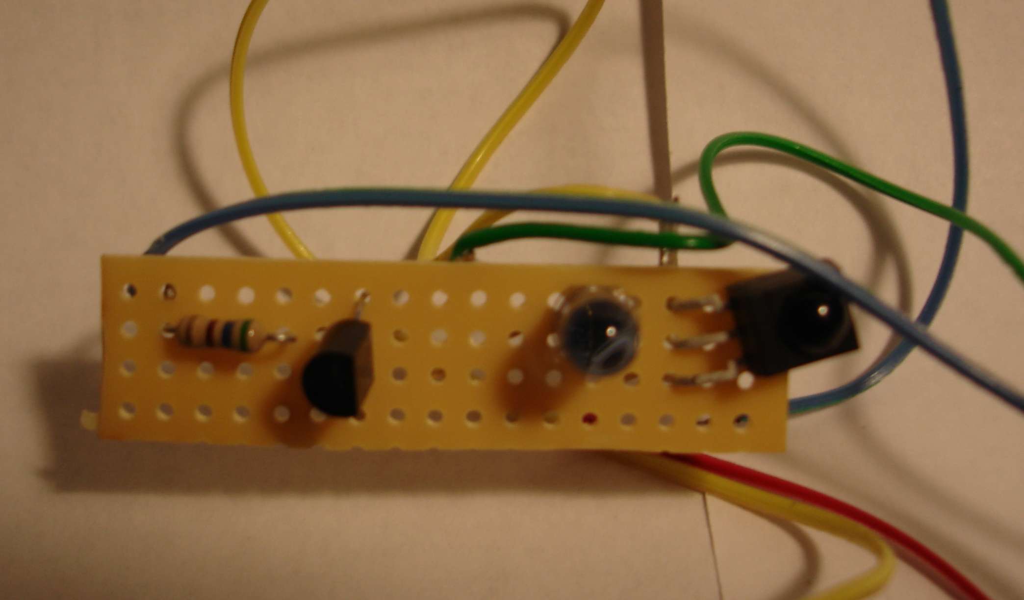
Homemade IR Transceiver Module
However sometimes the unit isn’t pointed in exactly the right direction the signal doesn’t get through. I needed something that was wider angle and perhaps more powerful. They make IR LEDs in either narrow angle or wide-angle versions. Perhaps if I had one of each or even to have each I would get the power I needed. There’s little gadget called a TV-B-Gone that is a battery-powered device with four IR LEDs and a pushbutton. When you push the button it will shut off any TV of any brand. People use it as a joke to walk into a place like a sports bar, electronic store, fitness center etc. and slyly turn off every TV in the place. I thought if I studied the output portion of the circuitry for that device maybe I could build my own little board that just did the transmitting and add my receiver to it.
Because I don’t know a lot about transistor circuit design I thought I would go to the discussion forums of my favorite parts place adafruit.com where they have an entire forum dedicated to TV-B-Gone and similar devices. They were very helpful in teaching me some basic circuit design skills and in advising me on this project. You can read the discussions here and here.
Here is another prototype version of my circuit using two LEDs. It’s based on information I learned from the people in the Adafruit forum. I call it my “IRIO Board” (Infra-Red Input/Output)
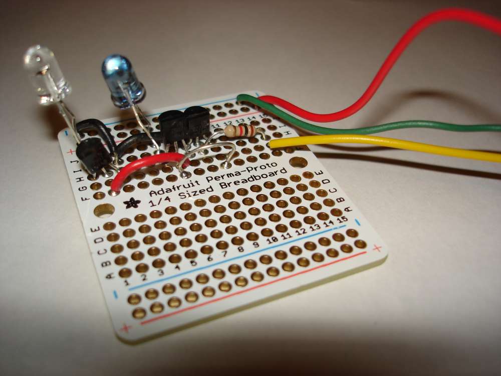
Prototype of My 2 LED IRIO Circuit
Part of the reason I wanted to redesign this little circuit was to try out a program called Eagle CAD from a company called CAD soft. It is available at http://www.cadsoftusa.com/ Is an expensive professional design program but there is a free version that will let you design small boards and certainly this one was small enough.
It gives you an extensive library of parts that you can use and there are ways to design parts of your own if you’re using a part that isn’t in the library. You basically do the design work on two different screens. On one of them you layout the schematic by dropping the pieces onto the screen, dragging them around with your mouse, and then connecting them together with wires. You then switch over to the circuit board portion of the program and arrange the components in the way you want them. On the circuit board side of the program, the components are already connected together with little rubber band like wires that stretch as you move the pieces around. There is a function called “rats nest” which helps you untangle the wires. Then you actually draw the traces to connect various parts together replacing the temporary rubber band wires with actual traces. In the free version you can only do a two player board top and bottom. The professional version allows you to do multiple layers. Two layers was going to be more than enough for me.
Here is the schematic that I designed. It has an NPN transistor driving up to 4 PNP transistors. Each of them in turn drives an IR LED. There is a 1k ohm that connects the NPN transistor to your Arduino board pin 3. There is also a place to put the IR receiver. In the schematic shown there are actually two IR receivers because I wanted to be able to mount the device pointing in different directions.
My IRIO Schematic from Eagle CAD
Here is a capture of what the circuit board screen looks like after I have arrange the pieces and put them in place. The red traces are on the top of the board. The blue traces are on the bottom layer. For those of you who are not familiar with it, the logo in the lower right corner is the “Open Source Hardware” logo. The four holes at the bottom are place to connect power, ground, input and output wires. There are a variety of ways you can put the IR receiver in the upper right corner.
My IRIO Board Layout in Eagle CAD
The white dotted lines show where you could cut off the left side of the board if you only wanted to use 2 LEDs instead of all four.
Now what to do with it? There are a variety of services which will take your Eagle CAD files and actually create the circuit board for you. If you tried to deal with a board manufacturer directly it would be very expensive. But there are services which take designs from a variety of hobbyists like myself, put all the little boards together on one big board, and ship it off to a manufacturer to be produced. They then take the big board, cut it apart, and ship it out to the hobbyists. I decided to use one such service called BatchPCB.com. You pay for the boards by the square inch plus a setup fee and shipping. My boards were under $5 each. I ordered three of them in with the other fees it was about $27. I placed the order on March 2 and it arrived yesterday on March 26. Here are front and back images of my professionally produced PCB board then I designed myself.
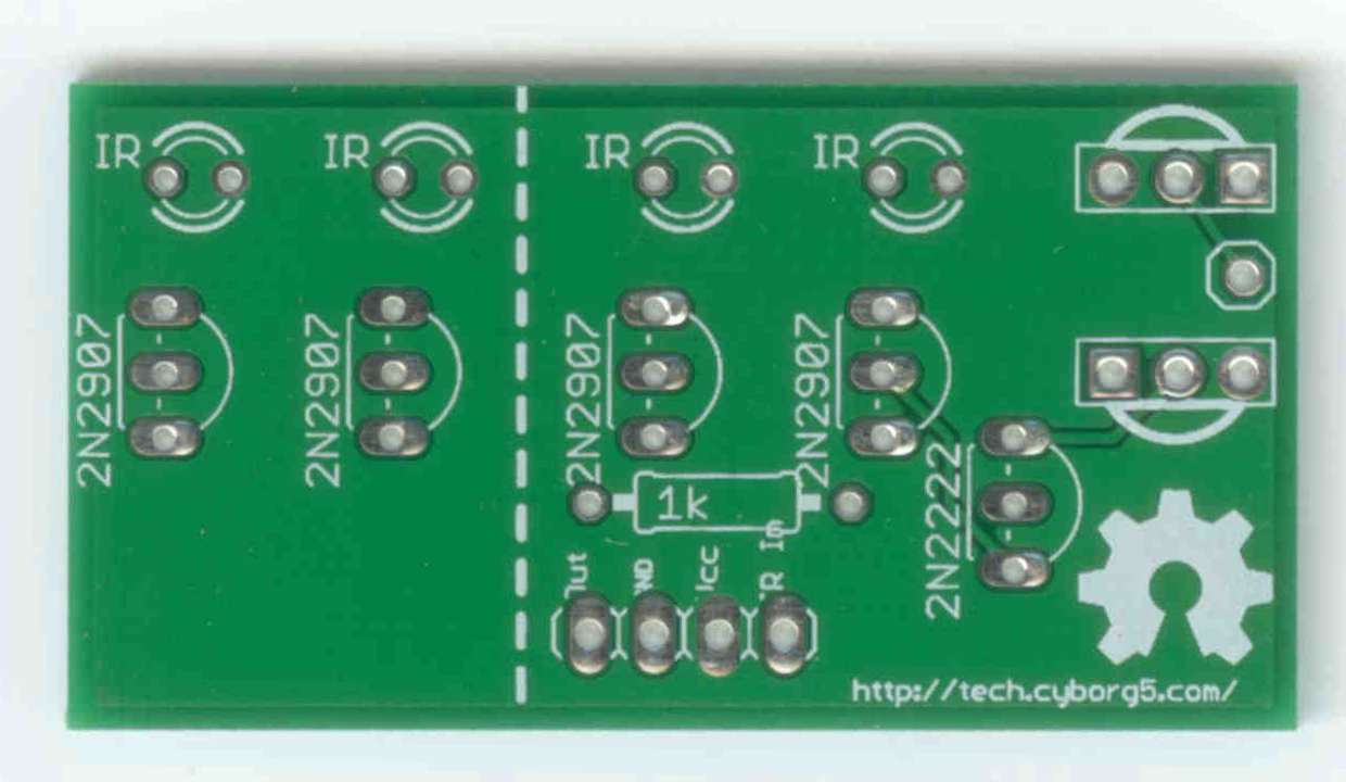
My IRIO Board (front)
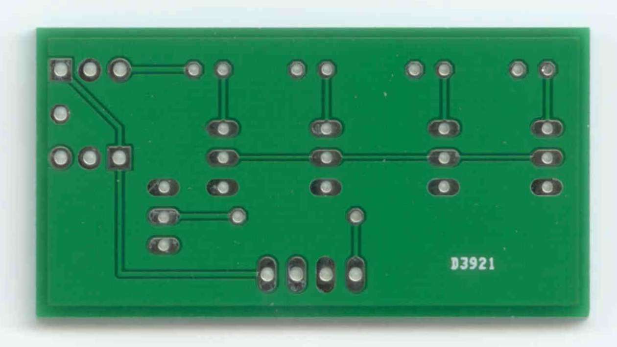
MyMy IRIO Board (back)
And finally… Here is what it looks like assembled. I tried it out and it works perfectly.
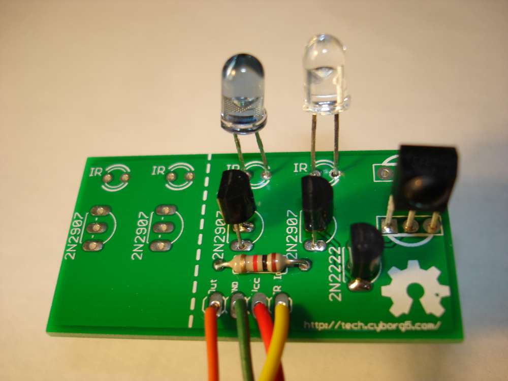
Assembled IRIO Board
This circuit however takes advantage of the fact that we are only sending brief pulses intermittently. We’re actually pushing more current through the devices then they are designed to take. One of the things I hope to do with this is to control an IR remote controlled toy helicopter. When pretty sure I will need to transmit signals continuously. So I designed another version of the board was some 33 ohm resistors to cut down on the current. Also when powering the Arduino from a PC USB port it draws too much current. It works okay on battery power or a USB charger but not directly on a PC.
I’ve submitted my new design to BatchPCB.com and hope to have it back in a couple of weeks. Here is a link to my updated board. It has not been tested on a real board but I did prototype it and it seems to work fine. I will post more information here when it comes. I also intend to write a tutorial on how to use this board with my IRLib Library for Arduino which you can read about here.
Why Is Bluetooth Called Bluetooth?
I recently found this great video that explains why Bluetooth is called Bluetooth.
Another Show and Tell Project
Here is a video about my latest electronic project. It’s a mouse and keyboard emulator that I use when my voice control program doesn’t do certain functions or gets hung up. You just plug it into a USB port, load a driver and use a TV remote to control the mouse, arrow keys or keyboard.
Adafruit Show-and-Tell sticker I earned for this presentation.
Playing House with Your Food
One of the strangest yet coolest electronic gadgets I’ve seen is an add-on for the Arduino microcontroller called “makey-makey” which allows you to turn ordinary household objects into touch sensor inputs to the microcontroller. From there you interface it to a music synthesizer (or other gadgets) to make them touch sensitive. Of all the uses of makey-makey that I’ve seen this video is probably the coolest. A guy uses a synthesizer/loop sequencer to create a cool version of the theme from the TV show “House”. Actually the name of the song is “Teardrop” by a group called “Massive Attack” but it’s better known as the theme from house.
For inputs he uses ordinary vegetables as touch sensors. Thus the title of this blog post. Enjoy!
I Can Now Zoom My IPod Touch!
As most of you know I operate my iPod touch using a wooden stick in my mouth. I had to put a metal tip on it to get it to activate the touchscreen but other than that it works really well. The only thing I haven’t been able to do is multi-finger gestures such as the pinch to zoom feature. There are other apps that have special features that require two or three finger swipes that I’ve never been able to do. For example there are some levels of Angry Birds that can only be solved by zooming out.
While doing some Google searches about accessible software I discovered that there has been a feature in the iOS operating system ever since version 5 (we’re now on version 6) called “Assistive Touch”. It puts a little floating icon on your screen that is there all the time. If you tap on it it allows you to do all sorts of different things such as rotate your screen, lock your screen, it’s the home key without using the physical button (which is very useful) and especially it allows you to do pinch to zoom and other multi-finger gestures! Here’s a video explaining the new improved features in iOS 6 regarding Assistive Touch. Here I didn’t even know it was in iOS 5! (Kind of embarrassing for technology geek like me).
That’s all for now… I’m off to finish up those levels of Angry Birds Space that I couldn’t do before.