Here is a video about the adaptive controller I made for a indoor IR toy helicopter. It allows me to use pushbuttons and an Arduino instead of the original joystick controller. I need the specialized controller because of my disability. Sometime soon I will post more details about this project and include source code.
The Greatest Music Video Ever Made
You could disagree with me that this is the greatest music video ever made but you would be wrong.
A Modern-Day Carnac the Magnificent: Bob the Robot
Last night on the weekly Adafruit show and tell video chat on Google+ hangouts maker Mike Barela showed off an ongoing project called “Bob the Robot”. The new feature he added for this week’s presentation was an RFID chip reader he had put on top of the robot’s head. He would then hold up a small card with an RFID chip in it and the robot would do his impersonation of the old Johnny Carson Tonight Show character Carnac the Magnificent. By holding the RFID card up to the head robot, the robot would speak an answer to the question written on the card. Here is the video from last night hangout…
Mike had attempted to recycle some old original Carnac jokes but expressed his frustration that many of them were outdated. That inspired me to write a more current script for the sketch…
Ed iMac Mann: We are honored tonight to have a famed visitor from the East! That famed sage, soothsayer, and unemployed Zilog chip designer Bob-nac the Magnificent.
Bob-nac: [walks on stage tripping over a step and sits down] Buzz click whir.
Ed: “buzz, click, whir”? Is that some sort of computer code?
Bob: No, it’s the names of my kids Buzz, Click, and Whir. Whir is my newborn. I was give them a shout out.
Ed: I have here in my hand the questions… They have been hermetically sealed in a rainbow colored Raspberry Pi enclosure and kept on the steps of Adafruit industry since noon today! No one… Absolutely no one knows the contents of these envelopes! But you in your borderline psychic and magical mystical ways will ascertain the answers to these questions having never before seen the questions themselves is that correct sir?
Bob: Affirmative!
[One by one Bob holds the cards up to his head and proclaims the answer]
Bob: Adafruit
[after each answer Ed opens the envelope and read the question]
Ed: What do you call a charity fundraiser for a sick banana?
Bob: Arduino Uno
Ed: What card game makers play when they aren’t making?
Bob: maker faire
Ed: What did the baseball coach tell the batter who keeps hitting foul balls?
Bob: Google hangout
Ed: Where do peeping toms go for a beer?
Bob: I hold in my hand the last envelope…
[Audience cheers]
Bob: May you trip and fall in a giant vat of Lady Ada’s pink hair dye.
[Audience laughs and groans]
Bob: The Harlem Shuffle, Eagle circuit design software, and Angelina Jolie’s husband
Ed: Name a fad, a CAD, and a Brad
In that same video I also showed off a couple of my projects. On the right is the Show and Tell badge that I earned and on the left the Python badge awarded to me for my first Python script despite the fact that I’ve been a programmer for 40 years. It made me feel like a kid again
IRLib Tutorial part 3b: Creating a Virtual Remote Using Python
 In the previous lesson we demonstrated how to send IR codes to a TV, DVD, DVR/cable box or any other device that uses an infrared remote. In order to tell the Arduino what code to send, we typed codes into the serial monitor of the Arduino IDE. While that’s great for demonstration purposes, it’s not very practical. In this continuation of the lesson, we will create a small program using Python which will create a “virtual remote”. This Python script will run on your PC, laptop or even Raspberry Pi which is connected to the Arduino. As you click on the buttons on the app, the script will send the proper codes over the serial link to the Arduino. The Arduino in turn will send the IR signals to your device. In addition to the items listed in part 3a will also need…
- a PC, laptop or even a Raspberry Pi with the Arduino connected to a USB port.
- Python 2.x programming environment installed
- PySerial add-on for Python that enables serial communication
- PyGame add-on for Python that makes it easy to use graphics, mouse, keyboard
- IRLib version 1.1 or later which includes the sample code
- IRLib version 1.1 including IRserial_remote examples and Python code
- Python language interpreter recommended 2.7.4 32 bit version
- PySerial 2.6 for any platform
- PyGame 1.9 for any platform
At the end of this tutorial we will post links to the Python, PySerial and PyGame packages. In part 3c of this tutorial we will give detailed instructions on how to install these passages on a Windows PC and a Raspberry Pi. When using Raspberry Pi it will probably already have Python and probably PyGame installed or you can find instructions on how to install them elsewhere online. We will include instructions on installing PySerial, the Arduino IDE and the IRLib packages on Raspberry Pi.
This example assumes you are using Python 2.7.x or later. Python 3 has some problems with serial communication especially in the Windows version. We also highly recommend installing the 32-bit version even if you have a 64-bit computer. We cannot guarantee this will run on 64 bits. Similarly when installing PySerial we recommend the 32-bit version.
Presuming you already have these packages installed we can proceed to customize a Python script to create virtual remote. In the previous installment we had you use the dump routine on your Arduino to capture the protocols, codes and number of bits for the functions you want to use. Our Python app can handle up to 40 functions however you can leave some of the buttons empty if you wish. But if you’re not yet done so, go back to the previous lesson and write down a whole bunch of codes you want to put in this new remote.
The Python script we will use is available in IRLib/examples/IRserial_remote/IRserial_remote.py. You also need the files “click.wav” and “remotebg.png” in the same folder. You will have to edit several lines of the script to customize it for your purposes.
A few lines into the script we will have to edit the serial port that the script we use to communicate to the Arduino. Look for these lines…
# You will have to edit this to the proper port and speed

ser = serial.Serial('COM4', 9600)
As distributed it is set to “COM4” but on a PC it might be some other COM port or on a Linux machine such as a Raspberry Pi it would be something like
ser = serial.Serial('/dev/ttyACM0', 9600)
We also need to specify what font will be used to put the labels on the buttons a few lines down like this…
# Specify a font. I'm using Arial narrow bold from my Windows

# font folder. However the default font shown below also works.

myfont =pygame.font.Font ("c:/windows/fonts/ARIALNB.TTF",30)

#myfont=pygame.font.Font(None,36)
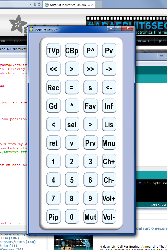
By the way if you are not familiar with the Python language it uses a hash tag at the beginning of the line to specify it is a comment. The default is a Windows font that is Arial narrow bold that you can specify your own font of choice or used default font by substituting the word “None” as shown above. Look for the section where we define the label text each button. Here are the values as distributed.
# These are the text labels that will appear on each button

label_text=("TVp", "CBp", "P^", "Pv",

           "<<", ">", ">>", "->",

           "Rec", "=", "s", "<-",
           "Gd", "^", "Fav", "Inf",

          "<", "sel", ">", "Lis",

          "ret", "v", "Prv", "Mnu",

          "1", "2", "3", "Ch+",
"4", "5", "6", "Ch-",
"7", "8", "9", "Vol+",
"Pip", "0", "Mut", "Vol-",
)
These correspond to TV power, cable box power, Page Up, Page Down, rewind, play, fast-forward, jump to live, record, pause stop, jump back, Up Arrow, favorites, info, Left Arrow, Select, Right Arrow, Lists Recordings, Return, Down Arrow, Previous Channel, Menu, numbers 1 through 9 and 0, Channel up, Channel down, Volume up, Volume Down, Mute, and PIP. However you can make them say anything you want.
Below that we insert the actual codes. We will use the same format we used in the previous lesson when we type codes into the serial monitor. First is a single digit that describes the protocol number, followed by a hex value, followed by the number of bits. Note that when some protocols the number of bits is optional. Here are the codes I used for a Magnavox TV using the “RC5” protocol and 13 bids And a Scientific Atlantic SA 8300 DVR using the PANASONIC_OLD protocols.
IR_Codes= ("3,180c,13","5,37c107","5,36d924","5,37d904",

           "5,37291a","5,37990c","5,36293a","5,36b129",

           "5,375914","5,374117","5,365934","5,37c906",

           "5,36c127","5,36812f","5,37f101","5,36213b",
"5,37810f","5,366133","5,364137","5,36c926",
"5,366932","5,37a10b","5,36e123","5,373918",
"5,36113d","5,37111d","5,36912d","5,377111",
"5,37910d","5,365135","5,375115","5,36f121",
"5,36d125","5,37d105","5,363139","3,1810,13",
"5,37b908","5,373119","3,180d,13","3,1811,13",
)
Once you have everything edited using your codes you should then load the IRserial_remote sketch into your Arduino. You can try typing a few codes into the serial monitor to make sure it’s working but once you are sure the sketch is running properly you need to close the serial monitor and the Arduino IDE so that they do not tie up the serial port. If you do not close at least the serial monitor, your Python script may not be able to connect to the Arduino properly.
Then run the Python script IRserial_remote.py script. A window should pop up showing a virtual remote control with 40 buttons on it looking something like this…
Notice as you hover your mouse over each button, the text will turn red. If you click on the button with the mouse it will make a clicking noise and it will instruct the Arduino send the proper IR codes. If everything works properly you should be able to control your device. Here is a YouTube video demonstrating how it works.
It’s not our intent to make this a Python tutorial so we will not go through the Python script line by line to explain how it works. Also included in the examples folder under IRserial_remote is a folder called “povray” which contains the source file for the Persistence of Vision Ray Tracer POV-Ray which is a freeware rendering program which was used to create the background image for the buttons on the remote.
Here is a video which demonstrates this application. This video was shown on the weekly Adafruit Show and Tell video chat on Google+ You can click on the “As seen on Show-and-Tell” logo at the top of this post to see it on the show and tell.
As promised here are links to various downloads you may need for this tutorial
In the next installment we will show you how to install these packages in case you haven’t already done so.
IRLib Tutorial part 3a: Sending IR Codes
In this lesson we will demonstrate how to send IR codes to a TV, DVD, DVR/cable box or any other device that uses an infrared remote. You will need…
- a 38 kHz IR receiver module,
- an IR LED and driver circuit such as described in part 1 of this tutorial,
- a TV, DVD, DVR or whatever device to control,
- an IR remote control for that device so we can obtain the proper codes.
Begin the process by wiring an IR receiver to pin number 11 on your Arduino as described in part 1 of this tutorial. Hook up an IR LED and a driver circuit also described in part 1 of this tutorial. If you are using Arduino Uno it will connect to pin 3. On the Arduino Leonardo you should use pin 9
Now you should load the IRrecvDump sketch from the examples folder of the IRLib library. We will use this sketch to determine what codes your infrared remote is transmitting. Run the sketch and open the serial monitor. This is the same process described in part 2 of this tutorial. Write down the received codes for all of the major functions of your device such as power on, channel up and down, volume up and down, rewind, fast-forward, play, stop etc. Also make note of the protocol and the number of bits. Here is what the dump for the power on function looks like on my Magnavox TV
Decoded RC5: Value:180C (13 bits)

Raw samples(24): Gap:30014

  Head: m850  s900

0:m900 s900	1:m1700 s900		 2:m900 s900	3:m850 s900

4:m850 s900	5:m850 s900		 6:m900 s850	7:m900 s1750

8:m900 s850	9:m1750 s900		 10:m900

Mark  min:850	 max:1750

Space min:850	 max:1750
As before, you only need to concern yourself with the first line of text. The protocol is “RC5” the code is “180C” and it uses 13 bits.
We are going to presume that you are using a remote that has a protocol that this library understands. If the top line of the dump says “Decoded Unknown” then you will have to skip ahead to section on how to program your own protocol in a future lesson of this tutorial.
Now load the following sketch named “IR_serial_remote” which is shown here. It is also available in the latest update to IRLib version 1.1 which was uploaded to GitHub on April 21, 2013 or later. This upgrade to the library also contains some other minor enhancements and a copy of the “IRservo” example used in part 2 of this tutorial.
#include
IRsend My_Sender;
int protocol;
long code;
int bits;
void setup() {
Serial.begin(9600);
}
long parseHex (void) {
long Value=0; char C;delay(100);
while (Serial.available()>0) {
C= tolower(Serial.read());
if ((C>='0')&&(C<='9'))
C=C-'0';
else
if ((C>='a') && (C<='f'))
C=C-'a'+10;
else
return Value;
Value= C+(Value<<4);
};
return Value;
}
void parseDelimiter () {
char C;
while(Serial.available()>0) {
C=tolower(Serial.peek());
if( (C>='0') && (C<='9') )return;
if( (C>='a') && (C<='f') )return;
C=Serial.read();//throwaway delimiters
delay (5);
}
}
// enum IRTYPES {UNKNOWN, NEC, SONY, RC5, RC6, PANASONIC_OLD, JVC, NECX, HASH_CODE, LAST_PROTOCOL=HASH_CODE};
void loop() {
if (Serial.available ()>0) {
protocol = Serial.parseInt (); parseDelimiter();
code = parseHex (); parseDelimiter();
bits = Serial.parseInt (); parseDelimiter();
/* Serial.print("Prot:"); Serial.print(protocol);
Serial.print(" Code:"); Serial.print(code,HEX);
Serial.print(" Bits:"); Serial.println(bits);
*/
My_Sender.send(IRTYPES(protocol), code, bits);
}
}
Upload the sketch and open the serial monitor. We will type in the protocol number, function code, and the number of bits for one of the functions that you wrote down. For example to turn on my TV I would type in
3,180c,13
The “3” is the number of the protocol that I’m using. If you look in “IRLib.h” at about line 50 you will see the following enum definition.
enum IRTYPES {UNKNOWN, NEC, SONY, RC5, RC6,

  PANASONIC_OLD, JVC, NECX, HASH_CODE,

  LAST_PROTOCOL=HASH_CODE};
You can send that “RC5” is the third protocol. In my examples I will also be using protocol 5 which is “PANASONIC_OLD” which is the protocol used by my Scientific Atlantic SA 8300 HD cable box/DVR.
After typing in the protocol number, code, and number of bits in the serial monitor you should press enter or click on the “send” button. The Arduino should decode this information and send the proper signals from your IR LED. If you want to make sure that what you are typing is getting parsed you can uncomment the “Serial.print…” statements near the end of the sketch.
Here are the details on how the sketch works…
We start by including the IRLib.h file for the library. We create the sender object and create some integers to store the protocol number, code, and number of bits. The setup routine simply initializes the serial port.
The standard Serial objects include routines for parsing integers in decimal format coming across the serial line but it does not include parsing hexadecimal values so we’ve written a little routine called
long parseHex (void)
Which accepts characters “0” through “9” and “A” through “F” either upper or lower case and converts it into an integer value. We also have a routine called
void parseDelimiter ()
It skips over any commas, blanks or other extraneous characters which you use as a separator.
The main loop simply looks for serial characters available, parses them, and then sends them using the send method as follows
My_Sender.send(IRTYPES(protocol), code, bits);
Note that because the protocol is actually an enum rather than an integer we have to typecast it when passing it to the send method.
Of course it would be quite tedious to have to look up the protocol number, hex codes, and number of bits every time you wanted to send a function. So we’re going to write a program which will send that serial data from your PC to the Arduino. We will create a “virtual remote control” in which you can click on buttons on it will send that serial data to the Arduino which will in turn control your device.
In part 3b we will show you how to use a Python script to create just such a virtual remote and send the codes from your PC or laptop to the Arduino.
IRLib Tutorial part 2: Controlling a Servo Using an IR Remote
 In this lesson we will demonstrate how to receive IR codes and to use that information to do something useful. In this case we’re going to position a servo. You will need
- a 38 kHz IR receiver module
- a servo motor that uses PWM for positioning
- an IR remote control for a TV or VCR or any such device
At the end of this blog we will link to some sources for these items. If you do not have a servo available you should be able to follow the code given here to control relays or turn on and off LEDs or any other function you might control with an Arduino microcontroller.
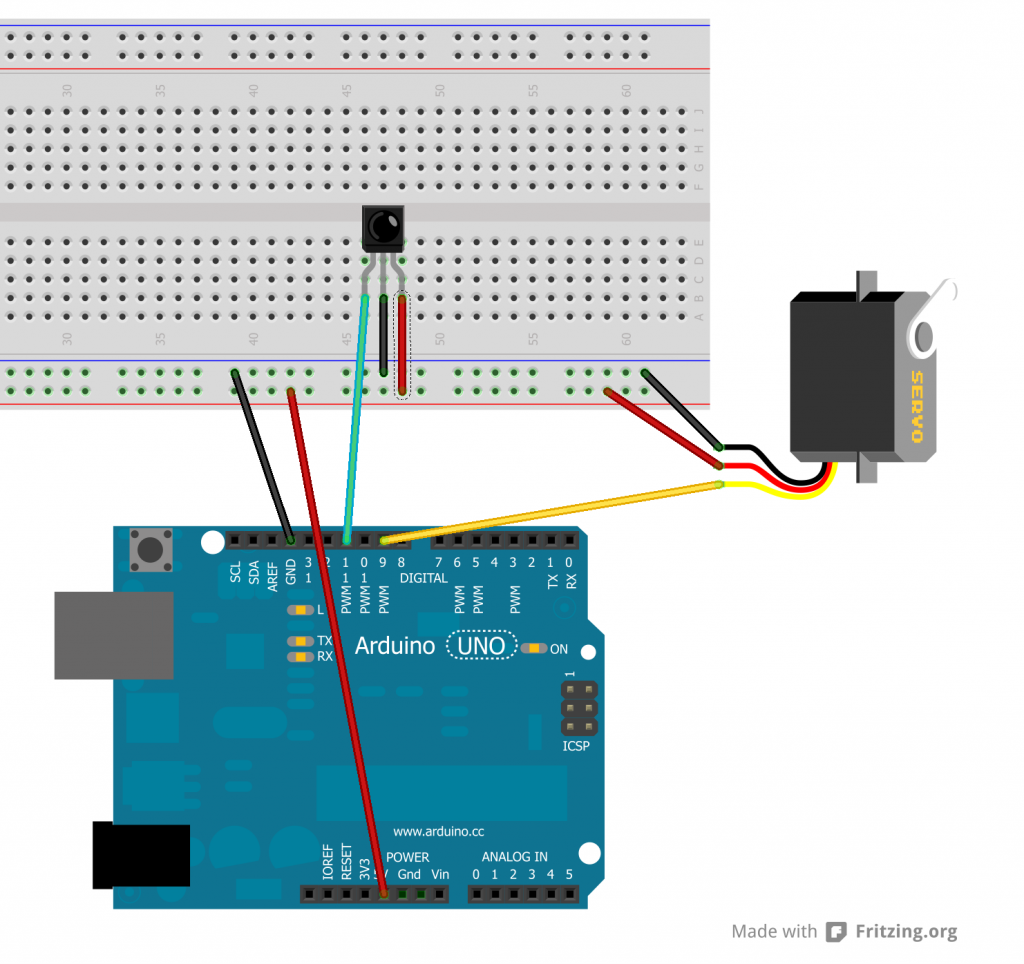
Begin the process by wiring an IR receiver to pin number 11 on your Arduino as described in Lesson 1 of this tutorial. For this example you do not need to hook up an IR LED. We’re going to be receiving only. Also hook up a servo motor to power and ground and to pin number 9 on your Arduino. This diagram shows the complete set up.
Now you should load the IRrecvDump sketch from the examples folder of the IRLib library. We will use this sketch to determine what codes your infrared remote is transmitting. Run the sketch and open the serial monitor. Point your remote at the receiver and press the right arrow button. In this example I’m using a remote from my Sony DVD/VCR. The output on the serial monitor looks like this…
Decoded Sony: Value:86BCA (20 bits)
Raw samples(42): Gap:12550
  Head: m2300  s650
0:m1200 s600 1:m550 s650  2:m550 s650 3:m500 s650
4:m550 s650 5:m1150 s650  6:m1150 s600 7:m600 s600
8:m1150 s650 9:m550 s650  10:m1100 s650 11:m1200 s600
12:m1150 s650 13:m1150 s600  14:m550 s650 15:m550 s650
16:m1150 s650 17:m550 s600  18:m1200 s600 19:m550
Mark  min:500  max:1200
Space min:600  max:650
We really only need to concern ourselves with the first line of text of this dump. It says that the protocol that was decoded was “Sony” and that the value was 86BCA which is a number in hexadecimal code. The remainder of the information is unimportant to us. You need to write down the value received for each of the following buttons: right arrow, left arrow, up arrow, down arrow, select, and the number buttons 0 through 9.
We are going to presume that you are using a remote that has a protocol that this library understands. If the top line of the dump says “Decoded Unknown” then you either need to use a different remote or skip ahead to section on how to program your own protocol in a future lesson of this tutorial.
Now load the following sketch named “IR_Servo” and we will modify it with the codes you have obtained. You can click on the little orange pair of scissors to copy the code into your clipboard.
/* Example program for from IRLib – an Arduino library for infrared encoding and decoding
 * Version 1.0  April 2013 by Chris Young http://cyborg5.com
 * "IR_Servo" Control a servo using an IR remote
 */
#include <IRLib.h>
#include <Servo.h>
// You will have to set these values depending on the protocol
// and remote codes that you are using. These are from my Sony DVD/VCR
#define MY_PROTOCOL SONY
#define RIGHT_ARROW   0x86bca //Move several clockwise
#define LEFT_ARROW    0x46bca //Move servo counterclockwise
#define SELECT_BUTTON 0xd0bca //Center the servo
#define UP_ARROW      0x42bca //Increased number of degrees servo moves
#define DOWN_ARROW    0xc2bca //Decrease number of degrees servo moves
#define BUTTON_0 0x90bca  //Pushing buttons 0-9 moves to fix positions
#define BUTTON_1 0x00bca  // each 20 degrees greater
#define BUTTON_2 0x80bca
#define BUTTON_3 0x40bca
#define BUTTON_4 0xc0bca
#define BUTTON_5 0x20bca
#define BUTTON_6 0xa0bca
#define BUTTON_7 0x60bca
#define BUTTON_8 0xe0bca
#define BUTTON_9 0x10bca
IRrecv My_Receiver(11);//Receive on pin 11
IRdecode My_Decoder;
Servo My_Servo;  // create servo object to control a servo
int pos;         // variable to store the servo position
int Speed;       // Number of degrees to move each time a left/right button is pressed

void setup()
{
  My_Servo.attach(9);  // attaches the servo on pin 9 to the servo object
  pos = 90;            // start at midpoint 90 degrees
  Speed = 3;           //servo moves 3 degrees each time left/right is pushed
  My_Servo.write(pos); // Set initial position
  My_Receiver.enableIRIn(); // Start the receiver
}

void loop()
{
    if (My_Receiver.GetResults(&My_Decoder)) {
       My_Decoder.decode();
       if(My_Decoder.decode_type==MY_PROTOCOL) {
          switch(My_Decoder.value) {
            case LEFT_ARROW:    pos=min(180,pos+Speed); break;
            case RIGHT_ARROW:   pos=max(0,pos-Speed); break;
            case SELECT_BUTTON: pos=90; break;
            case UP_ARROW:      Speed=min(10, Speed+1); break;
            case DOWN_ARROW:    Speed=max(1, Speed-1); break;
            case BUTTON_0:      pos=0*20; break;
            case BUTTON_1:      pos=1*20; break;
            case BUTTON_2:      pos=2*20; break;
            case BUTTON_3:      pos=3*20; break;
            case BUTTON_4:      pos=4*20; break;
            case BUTTON_5:      pos=5*20; break;
            case BUTTON_6:      pos=6*20; break;
            case BUTTON_7:      pos=7*20; break;
            case BUTTON_8:      pos=8*20; break;
            case BUTTON_9:      pos=9*20; break;
          }
        My_Servo.write(pos); // tell servo to go to position in variable 'pos'
       }
     My_Receiver.resume();
    }
}
First you need to tell it what protocol you have received. Edit it into the line which reads
#define MY_PROTOCOL SONY
In general want to use the protocol name that was shown in the dump routine but it must be in all capital letters. If you want to get technical about it, legal values for this item are shown in the file “IRLib.h” at approximately line 53 which looks like this.
enum IRTYPES {UNKNOWN, NEC, SONY, RC5, RC6,
  PANASONIC_OLD, JVC, NECX, HASH_CODE,
  LAST_PROTOCOL=HASH_CODE};
Now back to the sketch… You need to edit into the sketch the values which you copied down for each of your buttons on your remote. Note that since these are hexadecimal numbers you should precede each one with “0x”. So in our example for the right arrow which produced a value of “86BCA” the line should look like this…
#define RIGHT_ARROW 0x86BCA
Note that in hexadecimal numbers when the letters “A” through “F” are used you may use either upper or lower case letters.
Once you have all of the values edited into the sketch, you should upload it. The servo will automatically center itself when the sketch has been uploaded and runs. Point your remote at the IR receiver and press the right or left arrow on your remote. The servo should rotate right or left as you push the buttons. If you push the select button on your remote it should center of the servo again. Pressing the numbers 0 through 9 will position the servo to fixed points 20 degrees apart.
By default, when using the left and right arrow buttons, the servo will rotate left or right by 3 degrees for each push of the button. By using the up arrow or down arrow buttons you can change how far the servo rotates. If you press and hold the down arrow for a couple of seconds it will change the default rotation to 1 degree. Pressing the up arrow button increases it to a maximum of 10 degrees. You won’t see anything happen when you push up or down but subsequent presses of left or right will be faster or slower. Here is a YouTube video demonstrating the project.
Now let’s look at the sketch line by line to see how it works. Just below the section which you edited we define several variables and objects
IRrecv My_Receiver(11);//Receive on pin 11
IRdecode My_Decoder;
Servo My_Servo;  // create servo object to control a servo
int pos;         // variable to store the servo position
int Speed;       // Number of degrees to move each time a left/right button is pressed
We create a receiver object and tell it to look for codes on pin 11. IR codes consist of a series of on and off signals called marks and spaces. The receiver object is an interrupt driven routine that looks for a signal every 50µs. It then stores in a buffer of integers the length of each mark or space in 50µs intervals. The buffer is located in the decoder object so we pass the address of the decoder to the receiver. There are technical reasons why we have separated these processes into receiver and decoder unlike other IR libraries. We will get into that in a future must. As mentioned we also have to create a decoder object. The decoder object looks at the values and attempts to determine which protocol was used and what the data values are that were encoded in the signal. We also create a servo object. Details on the servo library can be found here in the standard Arduino documentation. And we need integers to hold the position and the speed of the servo.
In the “Setup” function we initialize the servo on pin 9 set some default values and give it the command to move the servo into the default position. You then have to use this line
My_Receiver.enableIRIn(); // Start the receiver
To initialize the IR receiver. In the “Loop” routine we have a single if statement that is constantly looking for an IR code.
    if (My_Receiver.GetResults(&My_Decoder)) {
       My_Decoder.decode();
The “GetResults(address)” function returns true if a code has been received. It puts it into the decoder object whose address you passed to it. You then call the “decode()” method of your decoder.
We next check to see if the results received were from the proper protocol. No need to go through a bunch of testing if you picked up a signal from a different remote. We check to see if the “decode_type” is the right one using this if statement. The variable “My_Decoder.decode_type” is an enum which was shown earlier in this lesson and can be found in “IRLib.h”.
if(My_Decoder.decode_type==MY_PROTOCOL) {
Finally we check the “My_Decoder.value” in a switch statement to see if any of our defined codes are what was sent. If none of the case statements are activated, the code just falls through and updates the servo at its previous position.
It is important that we restart the IR receiver after any signal has been received even if it’s not one that we were interested in. This is done with the following statement
My_Receiver.resume();
You could easily modify the sketch to handle multiple servos doing all sorts of things such as positioning a robot arm or steering a remote-controlled car or doing any other function. You could hook up LEDs that would turn off on depending on which button to press on the remote. You could hook up relays to turn lights on motors off and on.
As promised here are some links to the hardware mentioned in this post
- Arduino Uno available at Adafruit.com or RadioShack.com
- Arduino Leonardo available at Adafruit.com
- 38kHz IR receiver module available at Adafruit.com or RadioShack.com
- Servos such as used in radio controlled models. Here are just a few examples
- Standard Micro Servo at Adafruit.com
- High Torque Micro Servo at Adafruit.com
- Standard Servo at Adafruit.com
- High Torque Standard Servo at Adafruit.com
- Not that you would need it but here is a nice little IR remote control from Adafruit.com which used the NEC protocol supported by this library.
In the next lesson we will focus on transmitting IR signals.
My Second PCB Board
My First PCB Board
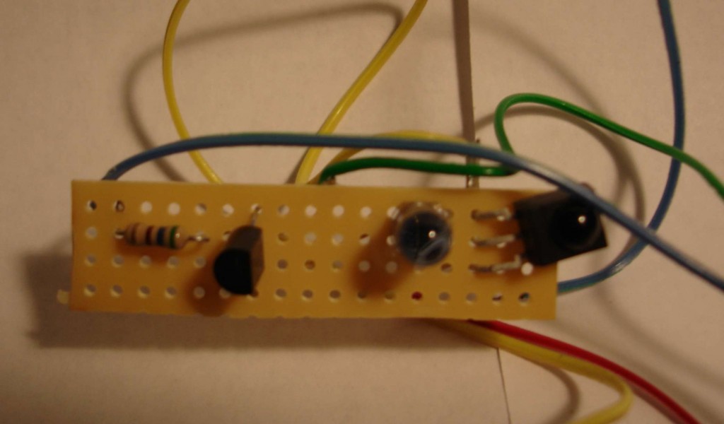
I’ve shared some videos on here talking about my infrared remote control that I built using Arduino Uno so that I could operate my TV and other devices with dozens of functions using only for pushbuttons. The device relies on a tiny circuit that has an infrared LED, a transistor, a resistor, an infrared receiver. The one that I’ve been using was thrown together on a little piece of perf-board that looks like this.
However sometimes the unit isn’t pointed in exactly the right direction the signal doesn’t get through. I needed something that was wider angle and perhaps more powerful. They make IR LEDs in either narrow angle or wide-angle versions. Perhaps if I had one of each or even to have each I would get the power I needed. There’s little gadget called a TV-B-Gone that is a battery-powered device with four IR LEDs and a pushbutton. When you push the button it will shut off any TV of any brand. People use it as a joke to walk into a place like a sports bar, electronic store, fitness center etc. and slyly turn off every TV in the place. I thought if I studied the output portion of the circuitry for that device maybe I could build my own little board that just did the transmitting and add my receiver to it.
Because I don’t know a lot about transistor circuit design I thought I would go to the discussion forums of my favorite parts place adafruit.com where they have an entire forum dedicated to TV-B-Gone and similar devices. They were very helpful in teaching me some basic circuit design skills and in advising me on this project. You can read the discussions here and here.
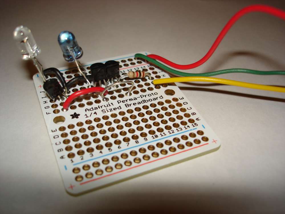
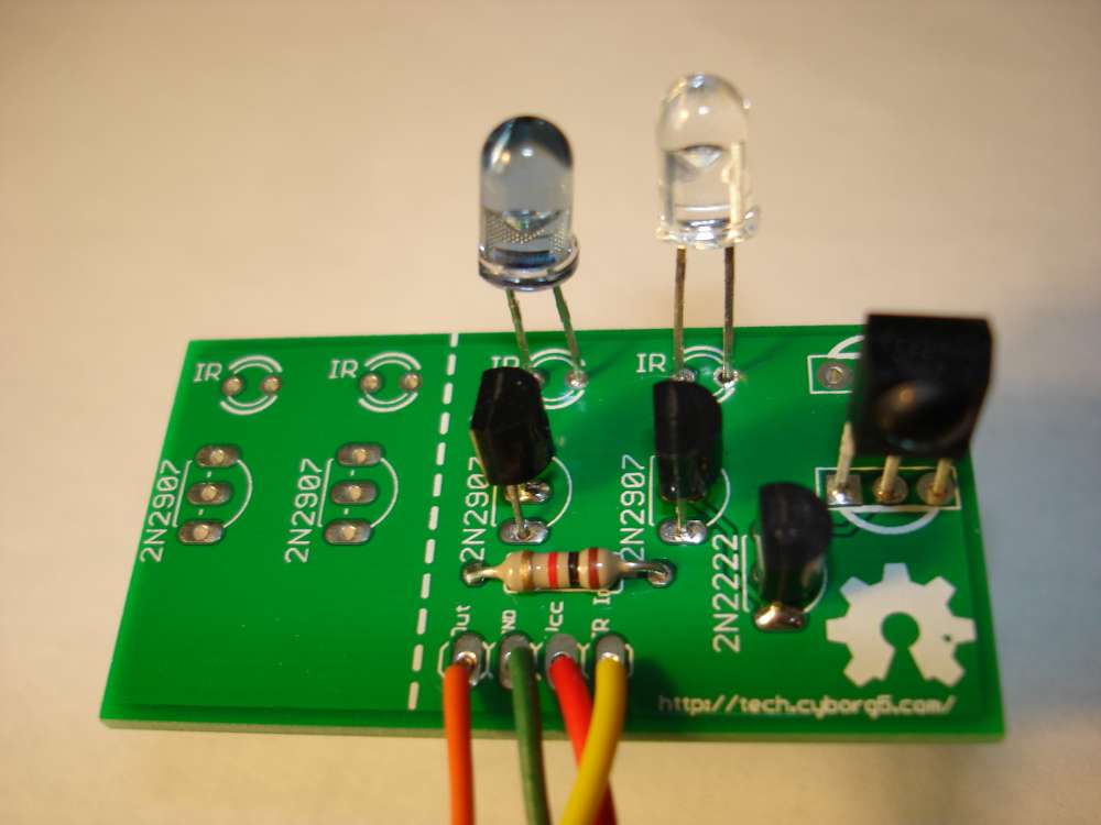
Here is another prototype version of my circuit using two LEDs. It’s based on information I learned from the people in the Adafruit forum. I call it my “IRIO Board” (Infra-Red Input/Output)
Part of the reason I wanted to redesign this little circuit was to try out a program called Eagle CAD from a company called CAD soft. It is available at http://www.cadsoftusa.com/ Is an expensive professional design program but there is a free version that will let you design small boards and certainly this one was small enough.
It gives you an extensive library of parts that you can use and there are ways to design parts of your own if you’re using a part that isn’t in the library. You basically do the design work on two different screens. On one of them you layout the schematic by dropping the pieces onto the screen, dragging them around with your mouse, and then connecting them together with wires. You then switch over to the circuit board portion of the program and arrange the components in the way you want them. On the circuit board side of the program, the components are already connected together with little rubber band like wires that stretch as you move the pieces around. There is a function called “rats nest” which helps you untangle the wires. Then you actually draw the traces to connect various parts together replacing the temporary rubber band wires with actual traces. In the free version you can only do a two player board top and bottom. The professional version allows you to do multiple layers. Two layers was going to be more than enough for me.
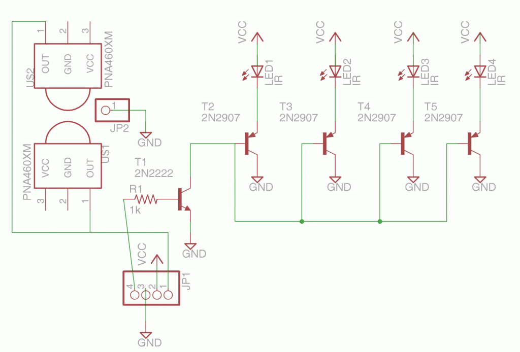
Here is the schematic that I designed. It has an NPN transistor driving up to 4 PNP transistors. Each of them in turn drives an IR LED. There is a 1k ohm that connects the NPN transistor to your Arduino board pin 3. There is also a place to put the IR receiver. In the schematic shown there are actually two IR receivers because I wanted to be able to mount the device pointing in different directions.
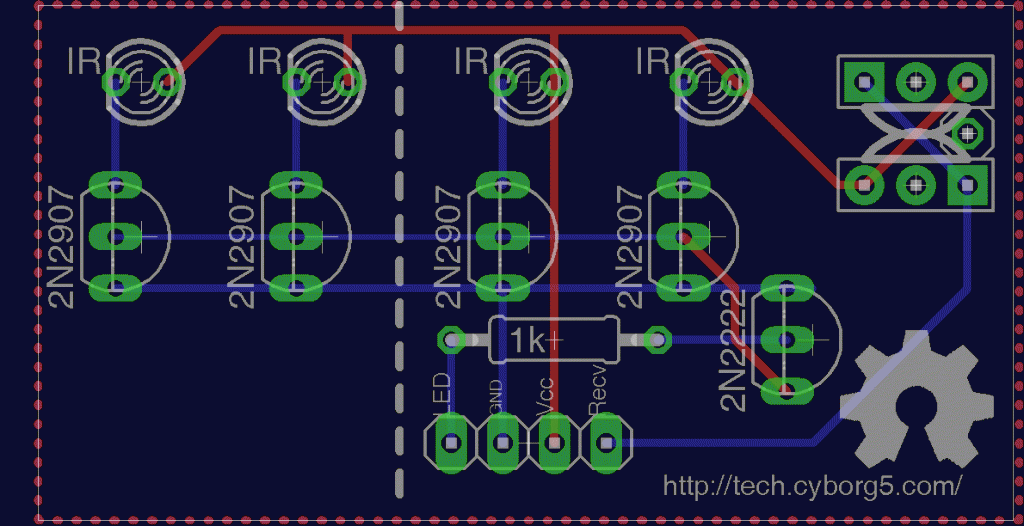
Here is a capture of what the circuit board screen looks like after I have arrange the pieces and put them in place. The red traces are on the top of the board. The blue traces are on the bottom layer. For those of you who are not familiar with it, the logo in the lower right corner is the “Open Source Hardware” logo. The four holes at the bottom are place to connect power, ground, input and output wires. There are a variety of ways you can put the IR receiver in the upper right corner.
The white dotted lines show where you could cut off the left side of the board if you only wanted to use 2 LEDs instead of all four.
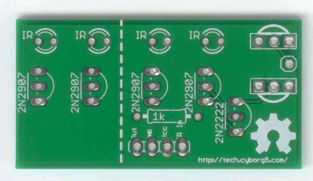
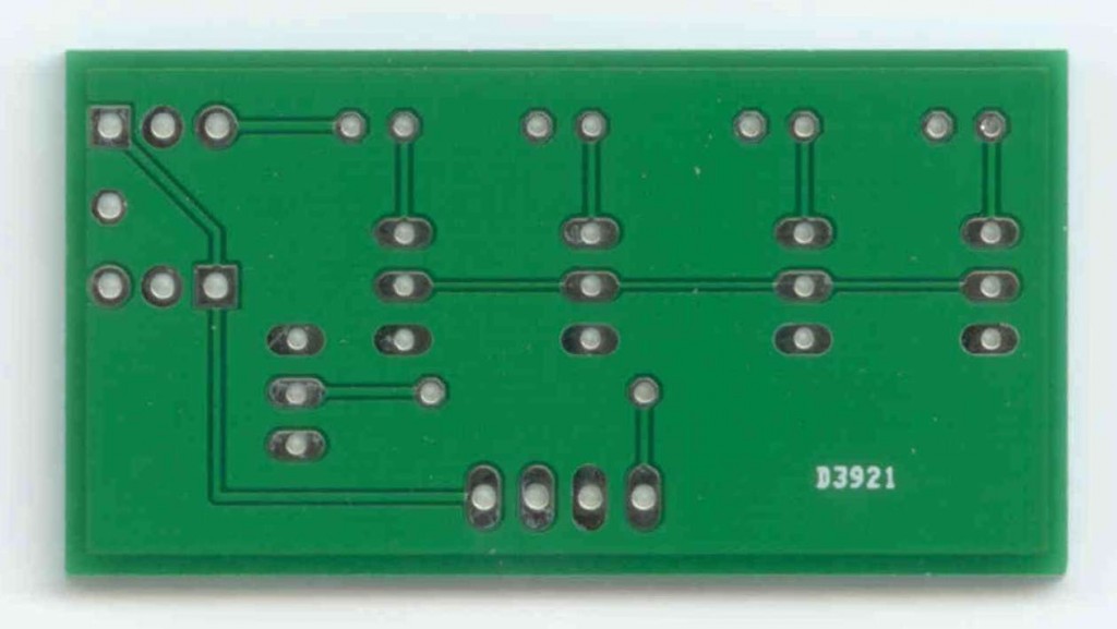
Now what to do with it? There are a variety of services which will take your Eagle CAD files and actually create the circuit board for you. If you tried to deal with a board manufacturer directly it would be very expensive. But there are services which take designs from a variety of hobbyists like myself, put all the little boards together on one big board, and ship it off to a manufacturer to be produced. They then take the big board, cut it apart, and ship it out to the hobbyists. I decided to use one such service called BatchPCB.com. You pay for the boards by the square inch plus a setup fee and shipping. My boards were under $5 each. I ordered three of them in with the other fees it was about $27. I placed the order on March 2 and it arrived yesterday on March 26. Here are front and back images of my professionally produced PCB board then I designed myself.
And finally… Here is what it looks like assembled. I tried it out and it works perfectly.
This circuit however takes advantage of the fact that we are only sending brief pulses intermittently. We’re actually pushing more current through the devices then they are designed to take. One of the things I hope to do with this is to control an IR remote controlled toy helicopter. When pretty sure I will need to transmit signals continuously. So I designed another version of the board was some 33 ohm resistors to cut down on the current. Also when powering the Arduino from a PC USB port it draws too much current. It works okay on battery power or a USB charger but not directly on a PC.
I’ve submitted my new design to BatchPCB.com and hope to have it back in a couple of weeks. Here is a link to my updated board. It has not been tested on a real board but I did prototype it and it seems to work fine. I will post more information here when it comes. I also intend to write a tutorial on how to use this board with my IRLib Library for Arduino which you can read about here.
IRLib Tutorial part 1: Hardware set up
This is the first in series of articles on using my infrared remote library for Arduino. In this installment we’re going to show you how to set up the hardware and how to run a quick demo sketch. You can find out more about the library on my IRLib page.
In order to detect a single from IR remote control such as you might use for your TV or home entertainment system you need an IR receiver module. Typically I use a unit I get from Radio Shack. You can also buy a similar module from my favorite supplier Adafruit.com. See the links at the end of this post for places where you can buy all of the parts mentioned in this article.
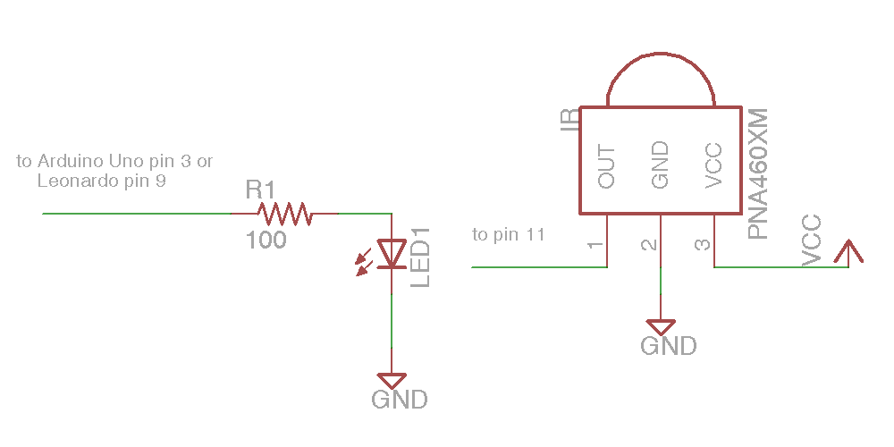
Pin 1 (on the left as you looking at the lens) needs to be connected to a input pin of the Arduino. It can be any could be any pin that doesn’t conflict with anything else you’re doing with the device. All of the examples in the library assume you are connected to pin 11 so we suggest you use it. The center pin 2 connects to ground any right-hand pin 3 should connect to your +5V power supply. If you are using a different microcontroller that runs at +3V this device will work at that voltage.
The simplest output device is simply an infrared LED and a current limiting resistor. IR LEDs can be purchased from a variety of places. Again see the links at the bottom of this post for sources. You are limited to using PWM pins for output because we use the PWM feature to modulate the signal. The default pin to use on Arduino Uno or other ATmega328-based controllers is pin 3. This particular pin is connected to “timer 2” of the chip. However the Arduino Leonardo and other controllers based on the ATmega32u4 does not have a “timer 2”. On these devices the default is to use timer 1 and pin 9 for output. We will talk more later about other options for timers and how to use this library on other types of hardware. For now all you need to know is if you have an Uno you should use pin 3 or a Leonardo use pin 11. Connect a 100 ohm resistor in series with the LED. Make sure you get the polarity of the LED correct. The shorter of the two leads should connect to ground. The longer lead connects to the resistor which in turn connects to the Arduino. Here is a schematic for the simplest setup. Note this post was edited on 2/5/2014 to correct the polarity. After telling you to be sure to get it right, I had described it wrong. The schematic has always been correct but my description was wrong. Sorry about that.
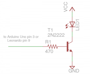
That was the absolute simplest schematic however the output from the IR LED will be pretty weak because the output pins of Arduino cannot supply much current. You might want to consider adding an NPN transistor to drive the LED.
Here is a schematic using a PN2222 NPN transistor and a 470 ohm base resistor with the LED. WARNING: This circuit will drive the LED beyond its continuous current limits of 100 mA. However because we are only pulsing the LED for a brief period using a modulated signal we can get away with this. So you should only use the circuit if you are certain that the output pin is not going to be left on continuously for more than a fraction of a second.Here is a simple sketch you can use to test if you are receiving IR signals. Is a stripped down version of the example sketch “IRrecvDump” that is in the examples subdirectory of the library.
/* Receiving IR signal and dump the details */

#include

//create a receiver object

IRrecv My_Receiver(11);//Use input pin 11
//create a decoder object
IRdecode My_Decoder;
void setup()
{
Serial.begin(9600);//We will read the output on the serial monitor
My_Receiver.enableIRIn(); // Start the receiver
}
void loop() {
//Loop until we get a signal and pass it to the decoder
if (My_Receiver.GetResults(&My_Decoder)) {
My_Decoder.decode();//decode the signal
My_Decoder.DumpResults();//dump the results on the serial monitor
My_Receiver.resume(); //restart the receiver
}
}
Upload the sketch and start the serial monitor on the Arduino IDE. Point a remote control such as a TV remote at the receiver and press a button. It will dump the information about the signal received. If it’s a protocol with the library understands it will tell you which protocol and it will give you a hex number of up to 32 bits that is the code for that particular function.
To test your transmitter, first determine the 32 bit hex code and protocol that the library can decode. A good example would be the power off/on button of your device assuming that your protocol is supported. As an example I sent a power signal to my Sony DVD player. The dump program tells me that it is a 20 bit code that is Sony protocol and that the value is 0xa8bca. The following sketch is a version of the example “IRsendDemo” in the examples directory of the library.
/*Transmit a power code for Sony DVD*/

#include
IRsend My_Sender;
void setup()
{
Serial.begin(9600);
}
void loop() {
if (Serial.read() != -1) {
//send a code every time a character is
//received from the serial port
//Sony DVD power A8BCA
My_Sender.send(SONY,0xa8bca, 20);
}
}
You will need to substitute the protocol name, the hexadecimal code, and the number of bits for whatever device you are operating. After you upload the sketch type a character into the serial monitor and press enter. Every time you transmit a character from the serial monitor, it will transmit the code you have programmed into the “My_Sender.send(…)” Function call.
In the installments which follow we will explain more of the details of the library including a more advanced circuit for transmitting codes. However for now this should get you up and running.
As promised here are some links to the hardware mentioned in this post
- Arduino Uno available at Adafruit.com or RadioShack.com
- Arduino Leonardo available at Adafruit.com
- 38kHz IR receiver module available at Adafruit.com or RadioShack.com
- IR LED available at Adafruit.com (single unit) or Adafruit.com (25 pack) or RadioShack.com
- 100 ohm resistor at RadioShack.com (5 pack)
- 470 ohm resistor at RadioShack.com (5 pack)
- NPN transistor at Adafruit.com (10 pack) or RadioShack.com
In the next installment will show how to receive and decode IR signals and use them to do something useful such as control a servo.
Why Is Bluetooth Called Bluetooth?
I recently found this great video that explains why Bluetooth is called Bluetooth.


