One of the hottest toys this Christmas is the Zoomer Dino. It is a remote-controlled self balancing two wheel robot dinosaur with an infrared remote. I got one for my 10-year-old nephew for Christmas and after playing around with it I had to get one of my own. I have been thinking about building Arduino powered two wheel balancing robot from scratch but here was one that works right out of the box. I’m not sure if it has a gyro or accelerometer to keep it balanced. He rolls around on his own making noises including burps, farts, and laughs. You can also take over control with an infrared remote. The remote has a joystick and three pushbuttons. The joystick moves the head up, down, left, right. If you hold in the “run” button while moving the joystick he rolls around under your control rather than moving the head. There also is a button for “chomp” which makes his jaw chomp open and closed. Additionally there is a “angry” button which makes his eyes glow red and he thrashes around angrily.
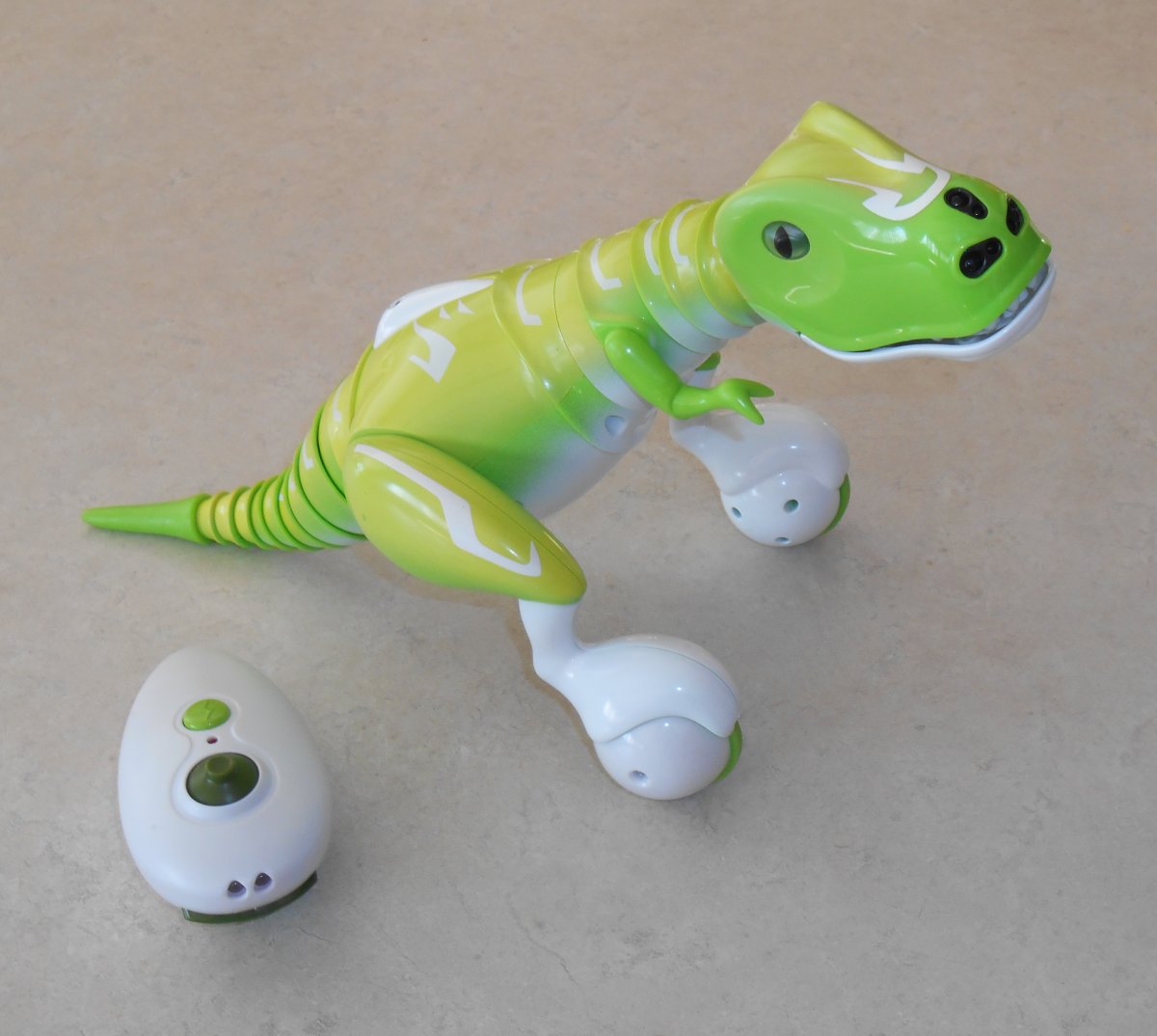
Zoomer Dino and IR remote
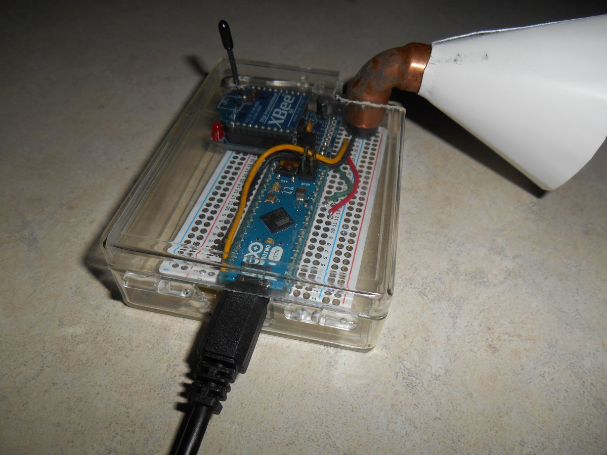
As with my IR controlled to a helicopter before, I had to see if I could reverse engineer the protocol it was using for the remote control. It was one of the most challenging IR reverse engineering projects I’ve ever encountered. I finally had to go out and purchase one for myself because I had to wrap up the original one for my nephew.
I used my IRLib Arduino Library for decoding and encoding IR signals. Once you push a button to get things started, the remote puts out a continuous signal that is the neutral position of the joystick with no buttons pushed. I came up with a raw dump of the timing values using my IRrecvDump sample sketch. Here are the results.
Decoded Unknown(0): Value:0 (0 bits)
Raw samples(54): Gap:43480
  Head: m9250  s4750
0:m550 s650	1:m500 s650		 2:m550 s650	3:m550 s1800
4:m500 s650	5:m550 s650		 6:m550 s650	7:m550 s650
8:m550 s1750	9:m550 s650		 10:m550 s650	11:m550 s650
12:m550 s650	13:m500 s700		 14:m500 s650	15:m550 s650

16:m550 s1800	17:m500 s1800		 18:m550 s650	19:m550 s1750
20:m550 s1750	21:m550 s1800		 22:m500 s1800	23:m550 s650
24:m550 s650	25:m500
Extent=53300
Mark  min:500	 max:550
Space min:650	 max:1800
This is a quite typical set of signals used by many protocols. Only the timings and number of bits are unique. We have a header that consists of about 9200 mark and 4800 space followed by 25 data bits and a closing mark. The data marks run about 500 or 550. The data spaces are either about 650 or 1800. This variable spacing is the most common way to encode zeros and ones. We’ll call the short spaces ones and the long spaces as ones. I created a custom decoder object as follows.
#include
#include

class IRdecodeDINO: public virtual IRdecodeBase
{
public:
  bool decode(void);
  void DumpResults(void);
};
#define DINO_HEAD_MARK   9200
#define DINO_HEAD_SPACE  4800
#define DINO_ZERO_MARK    500
#define DINO_ZERO_SPACE   650
#define DINO_ONE_MARK     500
#define DINO_ONE_SPACE   1800
#define DINO_SAMPLES 54
#define DINO_BITS 25

#define DINO (LAST_PROTOCOL+1)
void IRdecodeDINO::DumpResults(void) {
  Serial.print(F("Decoded DINO: Value:")); Serial.println(value, HEX);
};
bool IRdecodeDINO::decode(void) {
  IRLIB_ATTEMPT_MESSAGE(F("DINO"));
  if(!decodeGeneric(DINO_SAMPLES,DINO_HEAD_MARK, DINO_HEAD_SPACE,
    0, DINO_ZERO_MARK, DINO_ONE_SPACE, DINO_ZERO_SPACE)) return false;
  decode_type= static_cast<IRTYPES>DINO;
  return true;
};

IRdecodeDINO My_Decoder;

int RECV_PIN =11;

IRrecv My_Receiver(RECV_PIN);
long Previous;

void setup()
{
  Previous=0;
  Serial.begin(9600);while (! Serial);delay(1000);
  Serial.println(F("Send a code from your dino remote and we will decode it."));
  My_Receiver.enableIRIn(); // Start the receiver
}
void loop() {
    if (My_Receiver.GetResults(&My_Decoder)) {
    My_Decoder.decode();
    if(My_Decoder.decode_type == DINO) {
      if(My_Decoder.value!=Previous) My_Decoder.DumpResults();
      Previous= My_Decoder.value;
    }
    else Serial.println("Unknown");
    My_Receiver.resume();
  }
}
Because the remote sends signals continuously, this routine only reports the initially received value and then anytime the value changes to something different. It outputs 6 hex digits but note that there are 25 data bits being received. I then plugged the hex values into an Excel spreadsheet, converted them to decimal, and then parsed out the individual bits to try to deduce a bit pattern. I tried leaving the joystick alone when pushing the 3 buttons individually. Then I tried moving the joystick full throw forward, backwards, left, and right. The results are shown in the table below. You may click the table image to enlarge it.
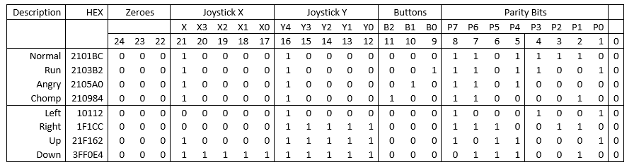
Table 1-Bit patterns from Dino remote.
In all samples, the first three bits were always zero as was the last bit. It was pretty obvious that after the initial zero bits, there was a five bit field that was the left/right position of the joystick with the left position having a value of zero, the center as 16, and the right was 31. This was followed by another five bit field that was the forward/backwards joystick position with zero to the back, 16 in the center and 31 full forward. The next three bits were obviously the three buttons. There were eight additional bits that seem to have no rhyme or reason to them.
Here is a revised version of the receiving code that parses out the bits into their individual fields.
#include

#include
class IRdecodeDINO: public virtual IRdecodeBase
{
public:
bool decode(void);
void ParseFields(void);
void DumpResults(void);
unsigned JoyX, JoyY, Parity;
char Chomp, Angry, Run;
};
#define DINO_HEAD_MARK 9200
#define DINO_HEAD_SPACE 4800
#define DINO_ZERO_MARK 500
#define DINO_ZERO_SPACE 650
#define DINO_ONE_MARK 500
#define DINO_ONE_SPACE 1800
#define DINO_SAMPLES 54
#define DINO_BITS 25
#define DINO (LAST_PROTOCOL+1)
void IRdecodeDINO::ParseFields(void) {
long Temp = value>>1;
Parity = Temp & 0x0ffL; Temp= Temp>>8;
Run = Temp & 0x1L; Temp= Temp>>1;
Angry = Temp & 0x1L; Temp= Temp>>1;
Chomp = Temp & 0x1L; Temp= Temp>>1;
JoyY = Temp & 0x1fL; Temp= Temp>>5;
JoyX = Temp & 0x1fL;
};
void IRdecodeDINO::DumpResults(void) {
ParseFields();
Serial.print(F("Decoded DINO: Value:")); Serial.print(value, HEX);
Serial.print ("\tJX:"); Serial.print(JoyX,DEC);
Serial.print ("\tJY:"); Serial.print(JoyY,DEC);
Serial.print ("\tCh:"); Serial.print(Chomp,BIN);
Serial.print (" Ag:"); Serial.print(Angry,BIN);
Serial.print (" Run:"); Serial.print(Run,BIN);
Serial.print (" Parity:"); Serial.println(Parity,HEX);
};
bool IRdecodeDINO::decode(void) {
IRLIB_ATTEMPT_MESSAGE(F("DINO"));
if(!decodeGeneric(DINO_SAMPLES,DINO_HEAD_MARK, DINO_HEAD_SPACE,
0, DINO_ZERO_MARK, DINO_ONE_SPACE, DINO_ZERO_SPACE)) return false;
decode_type= static_cast
return true;
};
IRdecodeDINO My_Decoder;
int RECV_PIN =11;
IRrecv My_Receiver(RECV_PIN);
long Previous;
void setup()
{
Previous=0;
Serial.begin(9600);while (! Serial);delay(1000);
Serial.println(F("Send a code from your dino remote and we will decode it."));
My_Receiver.enableIRIn(); // Start the receiver
}
void loop() {
if (My_Receiver.GetResults(&My_Decoder)) {
My_Decoder.decode();
if(My_Decoder.decode_type == DINO) {
if(My_Decoder.value!=Previous) My_Decoder.DumpResults();
Previous= My_Decoder.value;
}
else Serial.println("Unknown");
My_Receiver.resume();
}
}
But what to do about those parity bits? I had to presume they were some sort of checksum or other data verification field. Normally when capturing and decoding IR signals I really don’t care what the data represents internally. I point a TV remote at my receiver circuit, capture the hex value, and then re-create that value using my IR transmitter. I could have just quit now and build an application on the Arduino that would transmit button pushes and fixed joystick positions but it would be nice to be able to use any joystick position that I wanted from 0- 31 in either X or Y directions in any combination. But to do that I needed to figure out how to compute those additional eight bits of data.
Most consumer-electronics protocols use a simple checksum of adding the previous data fields together. Sometimes you take the 1’s complement of the data and repeat it. Sometimes you use bitwise XOR to combine the fields. I spent three days playing around with various versions of my Excel spreadsheet analyzing lots of bit patterns captured from the remote and could not deduce the pattern. I asked a couple of online acquaintances if they had any suggestions but they’re only input was to try checksum, XOR etc. A cyclical redundancy check or CRC was another option but that would be hard to reverse engineer and they generally are not used for such short streams of data. Keep in mind were only talking about 13 bits of actual data if you don’t count the leading and trailing zeros or the eight check bits.
At one point I remembered there was something called a Hamming error correction code. I had learned about them in college in my CS 484 class with Dr. Judith Gersting over 25 years ago. I barely understood how they worked back then and I’ve not used them ever since so the chances of me being able to figure it out on my own were represented by the three initial zeros in the data stream 🙂 Dr. Judith Gersting was not my only mentor in college. Her husband Dr. John Gersting told us on the first day of programming class that he was not going to teach us programming. He was going to teach us to teach ourselves programming because the minute we walked out the door, everything would probably be obsolete anyway. He literally handed us a textbook that he wrote and told us to go teach ourselves the course. I guess I was going to have to do some Google searches and teach myself everything I needed to know about Hamming codes.
As it turns out there is no one single way to create an error detecting/correcting code. There are entire websites devoted to multitudinous ways and they all use notation that I didn’t understand. I did find one website from UMass linked here.
http://www.ecs.umass.edu/ece/koren/FaultTolerantSystems/simulator/Hamming/HammingCodes.html
One thing I have learned about Hamming codes was that they typically only add a vary few extra bits. Using the calculator linked above if I put in a 16-bit value it would only add five additional bits. I was getting eight additional bits on just 13 bits of data. But the one thing I did learn from that page was the way you calculate those extra parity bits. There is a matrix that tells you which of the data bits to add together to get each of the individual parity bits. I really had to do was figure out which data bits contributed to each parity bit. I had already noticed that if you push the “run button” which I have listed as “B0”, that parity bits P2,P1,P0 all inverted from their normal position. Similarly the “angry button” which is “B1” toggles parity bits P3,P2,P1. Similarly the “chomp button” labeled “B2” toggles P4,P3,P2.
So I made a new set of columns in the spreadsheet to compute the parity bits. I begin by saying…
P0=B0

P1=B0+B1

P2=B0+B1+B2

P3=B2+B1

P4=B2
Additionally the center position of the joystick had only a single bit set, the highest order bit of the five bit field which was value 16. By comparing those to the joystick positions which were all of the way left or on the way back (which consisted of all zeros) I could figure out which parity bits changed based solely on X4 and Y4. Quite by chance I also found had captured samples with X positions of exactly 8, 4, and 2. So that told me which parity bits were based upon X3, X2, X1, and X0. As I updated the formulas for calculating each parity bit, I compared the computed results to actual capture values for every hex value I’d captured. I had a list of over 30 values that I had dumped from simply wiggling the joystick around. Eventually I was able to fill in the blanks and came up with the following formulas.
P0=X4+X0+Y4+Y3+B0

P1=X4+X1+Y3+B1+B0

P2=X4+X2+X0+Y3+B2+B1+B0

P3=X3+X1+Y4+Y0+B2+B1

P4=X4+X0+Y1+Y0+B2

P5=X3+X1+Y2+Y1+Y0

P6=X4+X2+Y3+Y2+Y1

P7=X3+Y4+Y3+Y2
Comparing my computed results to all my captured results I was convinced I had completely deduced how the parity bits were calculated. When you put those results in a table as follows, there is a definite pattern to them. It looks a lot like the patterns that had been seeing on various websites.
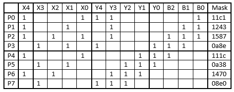
Table 2-Parity calculation matrix.
Finally I was able to create a sending routine that allowed me to test all of this out. This is a somewhat stripped-down version of what I ultimately came up with. You upload the sketch, call up the serial monitor, and type various characters into the monitor. The sketch then interprets those as commands and sends the proper hex code to the IR transmitter.
 #include

#include
class IRsendDINO: public virtual IRsendBase
{
public:
void send(unsigned long data);
};
#define DINO_HEAD_MARK 9200
#define DINO_HEAD_SPACE 4800
#define DINO_ZERO_MARK 500
#define DINO_ZERO_SPACE 650
#define DINO_ONE_MARK 500
#define DINO_ONE_SPACE 1800
#define DINO_SAMPLES 54
#define DINO_BITS 25
#define DINO (LAST_PROTOCOL+1)
void IRsendDINO::send(unsigned long data) {
sendGeneric(data,DINO_BITS,DINO_HEAD_MARK, DINO_HEAD_SPACE,
DINO_ONE_MARK, DINO_ZERO_MARK,DINO_ONE_SPACE, DINO_ZERO_SPACE, 38, true, 0);
delay(27);//Average gap was 26700 us
};
IRsendDINO My_Sender;
int RECV_PIN =11;
IRrecv My_Receiver(RECV_PIN);
char Mult, Normal, Chars;
#define COUNT 7
void SendMultiple(unsigned long Data, char Count) {
for(char i=0;i<(Count);i++) {My_Sender.send(Data);};
};
void setup()
{
Serial.begin(9600);;delay(2000);while (! Serial);delay(2000);
Serial.println(F("Enter one of the following letters A,C,U,D,L,R,F,B,<,>,N,0"));
Normal=1;
};
void loop() {
char Cmd;
if (Serial.available()>0) {
switch (Cmd) {
case 'A': SendMultiple(0x2105a0, 9); break; //anger
case 'C': SendMultiple(0x201984, 6); break; //chomp
case 'U': SendMultiple(0x21f162, COUNT); break; //head up
case 'D': SendMultiple(0x2000ae, COUNT); break; //head down
case 'L': SendMultiple(0x010112, COUNT); break; //head left
case 'R': SendMultiple(0x3f003a, COUNT); break; //head right
case 'F': SendMultiple(0x21f36c, COUNT); break; //forward
case 'B': SendMultiple(0x2002a0, COUNT); break; //backwards
case '<': SendMultiple(0x01031c, 5); break; //spin left
case '>': SendMultiple(0x3f0234, 5); break; //spin right
case 'N': Normal=1; break; //send neutral commands
case '0': Normal=0; break;//send wiggle commands
}
} else {//if no serial data then send either normal play mode or sit still
if(Normal) {
//Un-comment next line to have Dino do normal behavior.
// My_Sender.send(0x2101bc); //Comment out to turn off continuous transmission
} else { //wiggle slightly in an attempt to set still
My_Sender.send(0x21132c);
My_Sender.send(0x20f27e);
}
}
}
The actual remote sends continuous streams of data even when you aren’t doing anything. If you don’t touch any buttons or move the joystick for about one minute it eventually shuts down. If you are not pushing a button and the joystick is in the neutral position, the dinosaur engages in various preprogrammed behaviors. I needed a way to get him to sit still while I’m typing in the next string of letters. If you select “Normal” mode. It doesn’t send any signals. If you press a “0” it continuously sends a tiny forward and backwards code which basically has him sit in one place. He wiggles a tiny bit and make some noises but he doesn’t go off on his own. Then when you type other letters he goes in the direction you want him to. You can look at the “switch statement” to see which characters perform which functions. I send multiple transmissions of each code. The default number of signals is defined in COUNT so it was easy to change the default. I have a more advanced version of the sketch which causes him to move at various speeds, shake his head repeatedly, travel in zigzag motions etc. I also added commands to make him go forward and right or forward and left simultaneously. That way he doesn’t spin in place, he turns in a broad curve. In the demo video below I use that feature to make him travel in an oval-shaped pattern.
Know that all of the driving patterns I put him through in the video below could be done with the actual remote. You’ll have to trust me that they were created using an Arduino and my software.
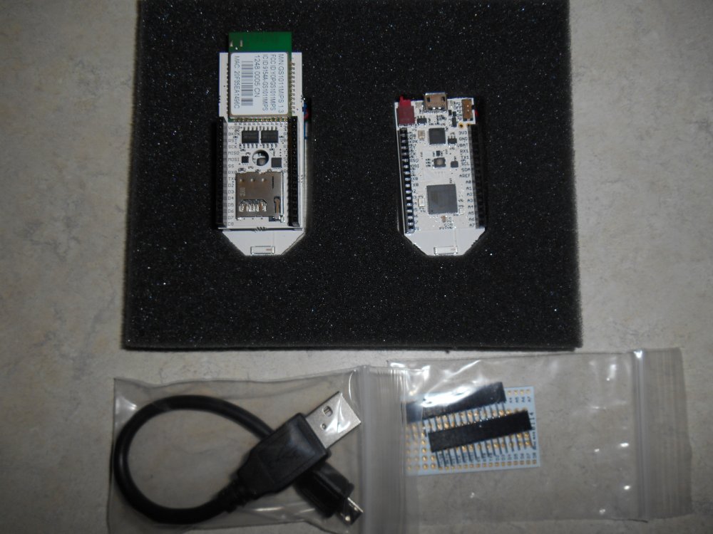
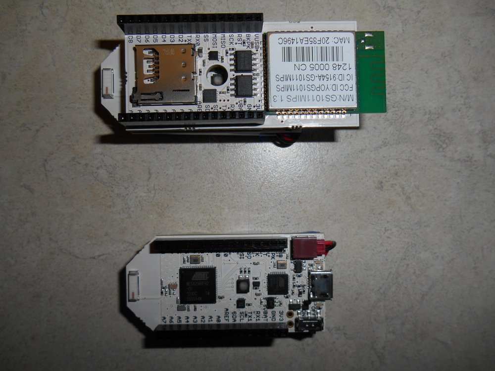
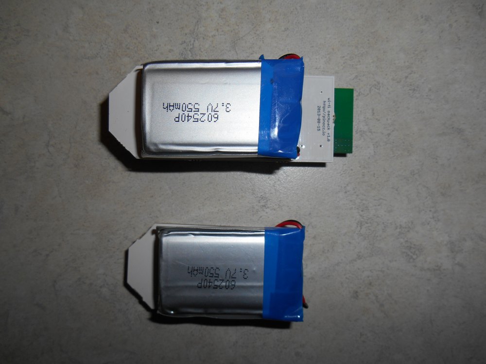
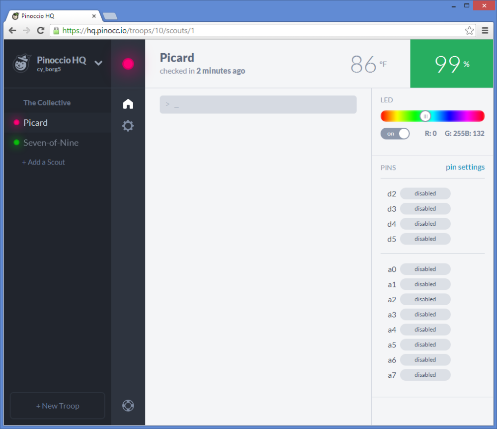
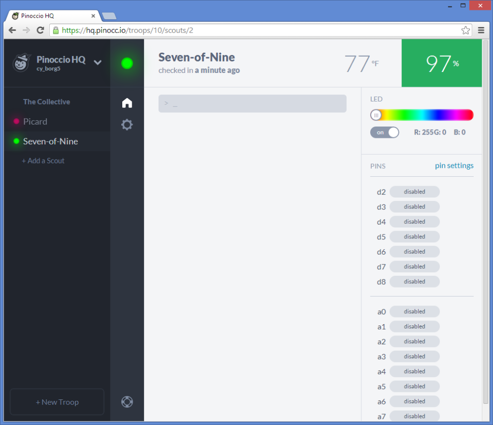
My ultimate goal is to port my code to my pinoccio board which includes Wi-Fi and mesh radio. That way I can control him through a webpage similar to this. I will end up with an “Internet of things” remote control dinosaur. The pinoccio has a LiPo battery and is very small. I might just velcro it with an IR LED to the back of the dinosaur and not worry about maintaining a line of sight from my transmitter. I will post more details when and if I ever get that working.
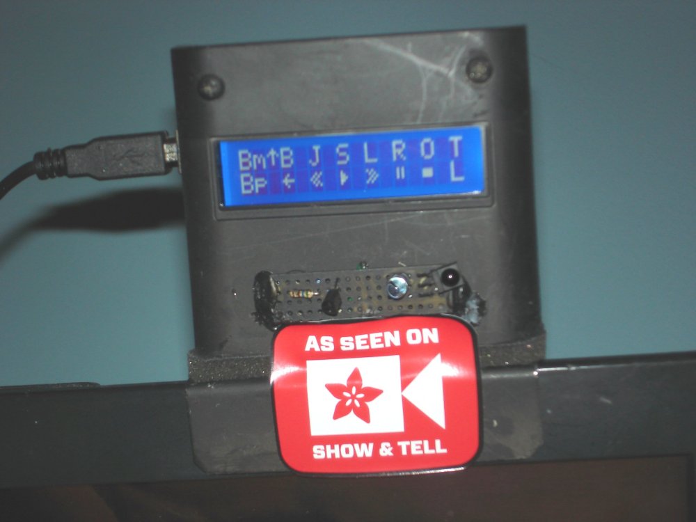
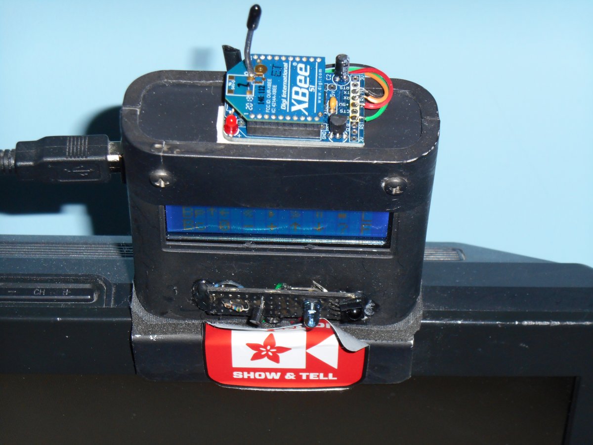
Here is where I demonstrated the project on the Adafruit weekly Show-and-Tell on Google Plus Hangouts.