In this installment we will cover the third and fourth days of working on the new wheelchair. We start to work on the new bib mount and continue to make other adjustments.
If the Shoe Doesn’t Fit…
We are now up to Wednesday which was the third day of the new wheelchair. We started out the day by sitting me in the new chair. Dad had previously shortened the foot rests so we were anxious to see how they fit. Somewhere along the way we miscalculated because both of the rest were still too low. For the time being we would put a pillow under my feet and dad would have to go back and get out the sawzall and shorten them even further.
The headrest wasn’t exactly like I wanted it but it was good enough to get me through the day. We would do more tinkering with that later. When the wheelchair technicians were here they had raised my left arm rest as high as it would go. It still wasn’t high enough but as a temporary measure we put a pillow under my left arm.
Getting In the Mode
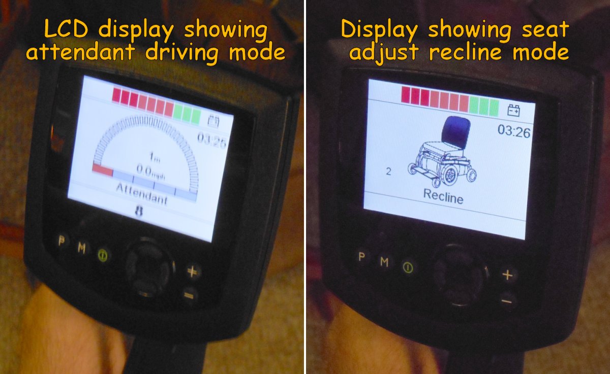
There is an LCD display mounted on the right arm rest. The chair has various modes that you can put it in for driving indoors or outdoors or for using the attendant controls. It also displays an image of the seat when you are in seat adjustment mode so you know which part of the seat you’re adjusting. For example when you push the mode button it would say one of the following “recline”, “tilt”, “recline and foot rest”, “both foot rests”, “left foot rest”, “right foot rest”. If you moves the joystick forwards or backwards it moves that item. If you tap the joystick left or right it moves to the next seat item such as going from recline to tilt and so on. Of course until I get a mode change button, I wasn’t going to be able to operate any of this.
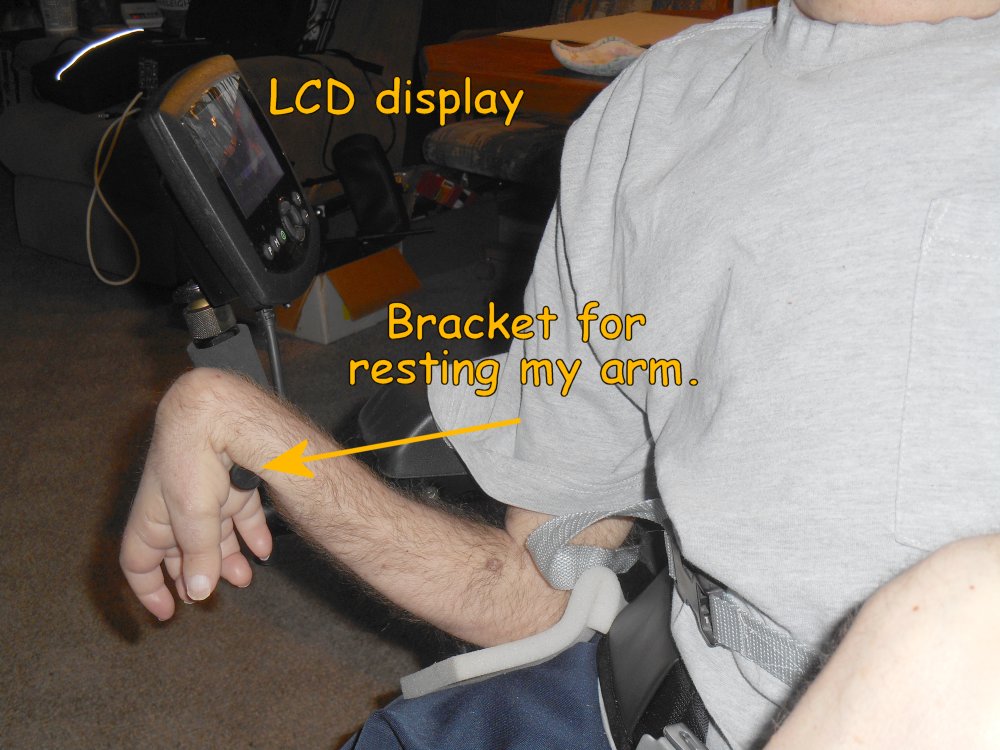
The LCD display was mounted pretty far forward sticking out in front of the armrest. It actually made the chair a little bit difficult to drive it through a narrow passage because it was sticking outside and so far forward. We would later adjust it so that it was not sticking outside or the front so far. When we got that adjusted, the little bar where the display is mounted actually is in a very good position where I can rest my right arm and still be able to hold the micro switches for my ultimate remote control.
I forgot to mention in an earlier post that I solved the mystery from the first day. When Patrick and tried to plug in the user control button for changing modes, it would turn the power off and on but would not change modes. That first night after I was in bed I got on my laptop and did some Google searches and found a PDF downloadable version of the technical manual. It turns out there are 3 places that you can plug in such a pushbutton. One of them is the user button for joystick port 1, the other is user button for joystick port 2, and the third one is for an extra power switch. He had been plugging the button into the wrong hole. That call to technical support was really unnecessary. I sent him an email the next day to tell him I had solved our mystery.
Anyway with a little adjustment we had managed to get me really comfortable. This would be my first full day sitting in the new chair and it turned out pretty good.
“For my yoke is easy”–Matt 11:30
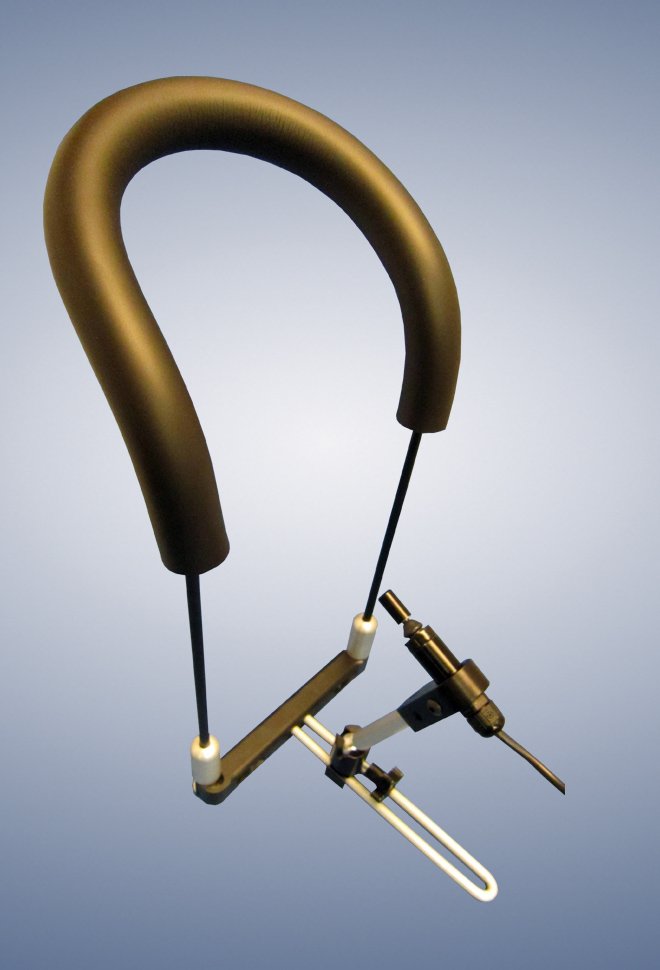
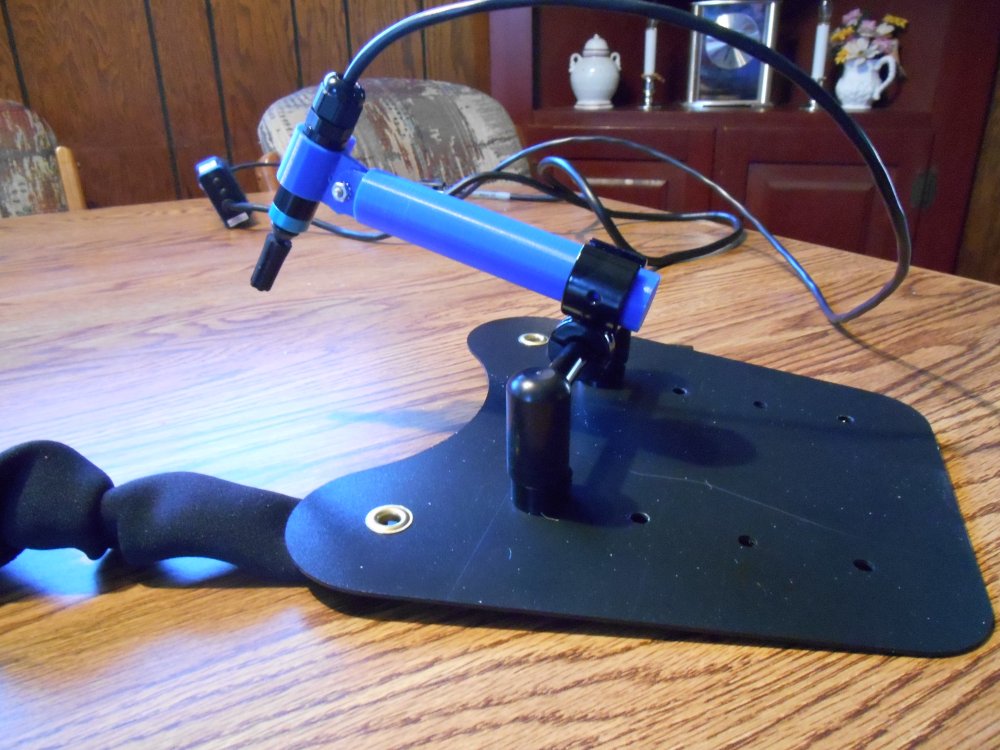
According to Matthew, Jesus says his yoke is easy but building a yoke around my neck to hold my new joystick was going to be quite a challenge. I had done a test drive using a bib mount from a company called “Switch It”. We are still using their joystick. However the bib was too tight around my neck and that’s why Patrick had replaced it with a different model that used straps instead of a solid bar. Unfortunately the straps would not hold the device steady enough. We could’ve told the wheelchair people to go ahead and order the original device from Switch It and we could’ve possibly bent it to fit. I had already thought about the possibility of building one from scratch after I saw the original test unit. Given the delays we had faced in getting any equipment at all the obvious choice was to build one ourselves. On the right is a photo of the gadget we were trying to re-create from scratch.
The main structure of the original one was a 1/4 inch or perhaps 3/8 inch aluminum rod bent in a U-shape. Dad found some one quarter inch stainless steel rod in the garage. It was left over from when he made some stainless steel weenie roast and marshmallow roast sticks that we used to use at the lake. He had no trouble bending it into the appropriate shape. The next job was to find some sort of foam tubing to slide over the bar to pad the device so that would not hurt my neck. I did lots of Google searches for foam rubber tubing and I found a place that would sell us exactly what we wanted and the cost was only $2 per foot. Unfortunately the minimum order was a 60 foot roll.
One of the great things about being a “maker” these days is that there are lots of makers out there was a wide variety of experience. There is a local maker space called “Club Cyberia” on the east side of Indianapolis that has a great bunch of people building all sorts of amazing projects. I visited their facility early last year to get some insight before buying my 3-D printer. I continue to follow all their activity on Facebook and I contribute to their discussions whenever I can. I asked them on Facebook if they knew of a place to buy foam tubing. They suggested the local industrial supply place called Grangers. We have had a Grangers catalog in this house for as long as I can remember. Dad buys all sorts of stuff from them for work or for his own projects. I felt kind of silly not thinking of them. Unfortunately they didn’t have anything small enough to meet my needs.
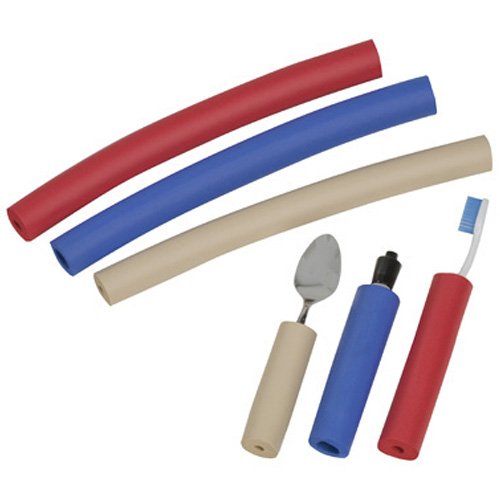
Meanwhile further Google searches found the following item on Amazon.com. It is a package of for long pieces of foam padding of various sizes and colors made by a company called “Ableware”. It is specifically intended for people who have physical disabilities and have trouble grasping ordinary objects like spoons, forks, toothbrushes etc. as you can see in the photo below. I immediately ordered a package on Amazon prime and it would arrive by Friday.
Now we turn to the mechanical portions of the mount. The two halves of the U-shaped bar are joined by a plastic bar that goes across them. I would have no trouble 3-D printing that. It’s just a straight bar with a hole on each end for the rod to go through. On the original Switch It bib mount they had a complicated set of ball and socket joints that allowed you to twist, bend, or pose the position of the joystick. I wasn’t sure that 3-D printer plastic was sturdy enough to create ball and socket joints with set screws to hold them in position. Also I wanted it to be as small and lightweight as possible but it is very difficult to print extremely small parts on a 3-D printer.
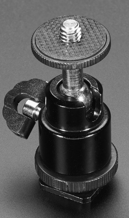
I did know where I could get parts that might do the trick. It was another instance of what I previously described as “just-in-time technology”. That is my term for the rather creepy experience I have had that whenever I need new technology to solve a particular adaptive equipment need, either by amazing luck or more likely divine providence that technology suddenly becomes available. Shortly after I did the first test drive with the bib mount and was thinking about what it would take to re-create one from scratch, my favorite electronics supplier Adafruit.com started selling some camera mounting hardware. I was especially interested in this ball and socket tilt and swivel camera mountshown on the right. It may seem strange that electronics company is selling camera mount equipment but they have all sorts of maker products. The camera mounts are featured that product in a tutorial on how to build your own computer controlled, motorized sliding camera mount useful for nice professional looking videos and time-lapse photos. Here’s a link to the tutorial. Here is a YouTube video showing how they created the mount.
They also added a couple of other camera mounting products like 1/4 inch screw adapters and set screws as used on camera mounts. So I went to the Adafruit store online and ordered a variety of parts which would arrive on Monday.
Each Wednesday night Adafruit hosts a live video chat using Google hangouts. If you have a WebCam you can join the discussion and show off your maker projects. I’ve done it a number of times before. Most people hold up their projects to the WebCam to demonstrate what they built but that’s a little bit difficult for me. I got in the habit of just having dad take photos of my gadgets. I use the same photos here on the blog or for showing off at the weekly Show-and-Tell. I spent the rest of the day on Wednesday preparing some photos of the 3-D printing parts I had already made for the joystick mount and to preview the fact that I was going to be using Adafruit parts and the rest of the design. Here is the video of my presentation on that particular evening. My section of the program starts at the 18 minute mark. The guy who presented just before me was so long-winded they couldn’t get him to shut up.
“Evening came and morning followed — the third day” — Genesis 1:13
A Minor Disaster
On Thursday, the fourth day of the new wheelchair, I decided not to sit in it so that dad could do more adjustment on the foot rest. That morning we got a phone call from my uncle Keith who said he wanted to stop by and visit that afternoon. His daughter, my cousin Nancy, recently passed away. She had spent her life in a wheelchair because she was born with spina bifida. Keith brought us a big box of leftover parts from some of her old wheelchairs. They were mostly headrests, brackets, and foam padding pieces. We figured there was something in there that we might be able to use. As it turned out they headrest that I ended up using was one that he brought us. Other pieces of foam padding also turned out useful for placing between my right side ribs in the armrest of the wheelchair and is a temporary pillow for the left arm rest until we can come up with something. We spent the entire afternoon visiting with him and talking about all of the troubles that Nancy had been through fighting her illness. I also had the opportunity to show him my 3-D printer. I made a souvenir for him. A 3-D printed thing to hang on your keychain. It had his name on it in raised letters.
That evening we did some tinkering with the new chair. Dad had noticed that when he tried to operate it using the mouse controlled joystick that the display unit would show “joystick error”. I had him push the buttons to get it into programming mode to see if I could figure out what was configured improperly. The process for pulling up the programming mode is to hold down the “Profile” button which is used to switch the chair from different driving profiles such as indoor, outdoor, attendant. While holding that button down, press and hold the power button. Then you release the profile button and wait for a beep. Then you release the power button. An icon of an hourglass appears on the LCD screen briefly and then you get into a series of menus. I had been studying the technical manuals and was pretty familiar with what was available in these menus. We tried swapping the joystick between port 1 and part 2 and doing other adjustments but we kept getting the joystick error message. I later learned that one of the things that can cause this problem is that the joystick was not properly calibrated in the programming menu. I began to speculate that this particular setup step had not been done given my discovery that the wheelchair technicians seemed unfamiliar with the contents of the technical manuals.
At some point something went wrong. The joystick stopped working altogether. You could still operate the attendant joystick in the back of the chair but nothing else seem to work. It was stuck in the attendant profile. I figured that was no problem. I would just go back in and undo whatever setting I had previously done. Unfortunately pushing the buttons in the proper sequence as I described above would no longer get me into the programming menus. We tried using 2 different joysticks plugged in either port. We tried pushing the buttons slower or quicker. Nothing that we did could get us back into the programming menus.
It was only the fourth day that I owned the new wheelchair and I had broken it already.
“Evening came and morning followed — the fourth day” Genesis 1:19
In my previous installment I described the events leading up to the delivery of my new wheelchair and the arrival itself. In this installment we will talk about what happened over the next day or two as I try to adapt everything to my needs.
Finally I NEED a 3-D Printer
When the prices of 3-D printers began to get reasonable, I began lusting for one almost uncontrollably. The only thing that held me back with the concept that no matter how much I wanted one I didn’t really have any use for one. I think that’s the dilemma most 3-D printer owners face. They are cool gadgets that you just want to own. You can do lots of neat things with them. But do you really “need” one? Finally my wants outweighed my lack of needs and I indulged myself as a 60th birthday present and bought one. While I have made some useful plastic boxes for my electronics projects and made some fun toys and Christmas ornaments, I still really didn’t “need” a 3-D printer until right now.
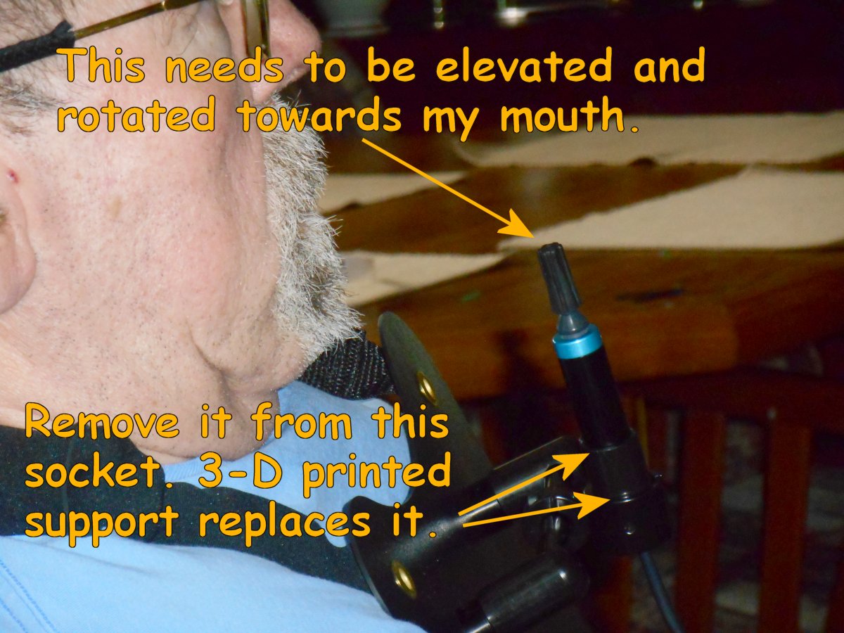
In the previous post I showed that the bib mount for the joystick was designed for chin use and not mouth use like I had planned. No amount of adjusting it was going to get the joystick up to my mouth. I was going to need to build a new bracket to reposition it. The 3-D printer with the perfect solution to this task.
After the wheelchair technicians left, we had supper and then I went straight to my office to begin designing the new bracket. As you can see in the image below, the joystick is sitting in a round socket. It is held there by a small set screw. I can remove the joystick from the socket, build a new support that fits there. Then I can mount the joystick in a new socket on top of the bracket. I also need it to be able to tilt up or down to adjust the position and angle of the joystick.
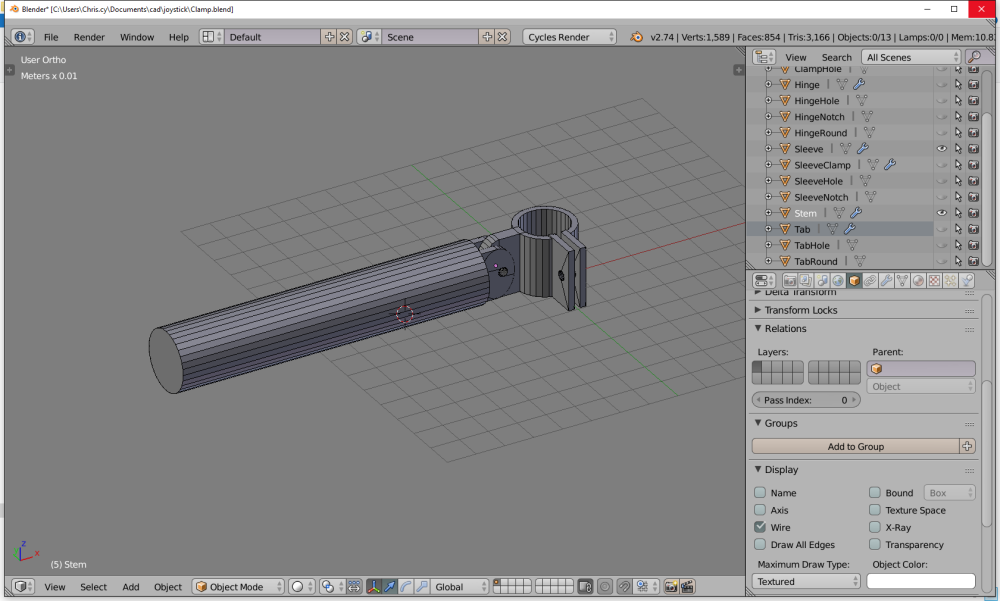
Here is what the part looks like in my CAD design program called Blender 3-D. The bracket is in two pieces. There is a long cylinder object that will fit into the socket where the joystick used to be. On top of that is a new socket to hold the joystick. It can pivot forwards and backwards and will be held to the long piece with a screw. The new socket can be tightened with a screw as well so it will grip the joystick.
I got the design pretty much done the evening of the day the chair arrived but I didn’t have time to print it. I ate my usual snack and went to bed. But it was nearly impossible to sleep thinking about all the modifications we needed to do on the chair.
“Evening came and morning followed. The first day.” Genesis 1:5
Dad and I Do Our Thing
It’s now Tuesday March 29 and Dad and I sort of got into our “Liam Neeson in Taken” mode. To paraphrase the movie “we are men with a particular set of skills”. For my part that means putting the final touches on the CAD design for my new bracket. For dad it means getting out his power sawzall and power drill and getting to work shortening my foot rests. Because he was going to be working on the chair and we still didn’t completely have the headrest and other comfort items adjusted properly, I spent the day in my old wheelchair.
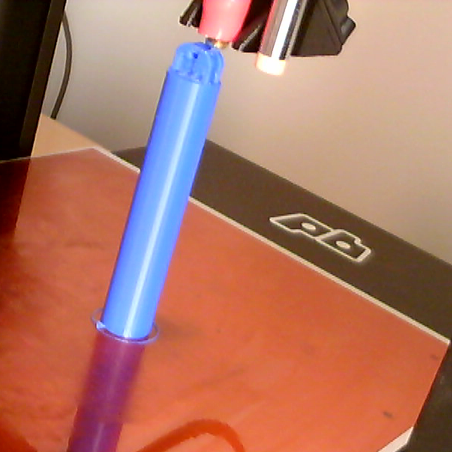
When printing objects on a 3-D printer. It’s best if you have a flat surface on the bottom. So the cylindrical parts of the bracket couldn’t lie down on their side or they would have a flat side and they would not come out very cleanly. So the tall part of the bracket has to stick straight up in the air. It’s about four and half inches long. I had never printed a tall skinny piece like this before. I was worried it would come unstuck and fall over. Fortunately it printed just fine as you can see here.
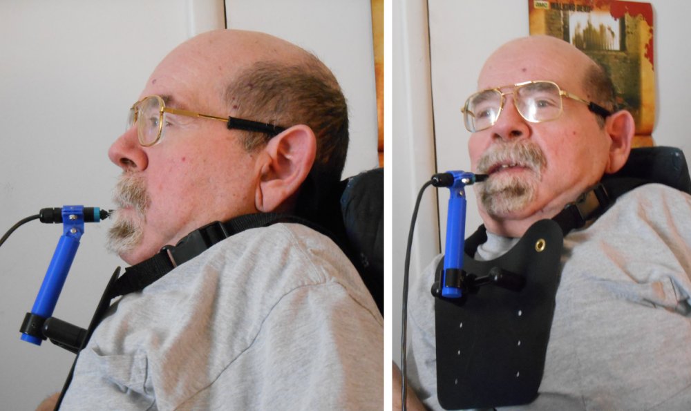
When I completed it, dad took a break and assembled my creation. Like always, you occasionally have to do a little filing or scraping objects to get them to fit together precisely but it wasn’t too hard to assemble. I had made a small test piece to get the tolerances right. Here is a photo of the device assembled just like I had planned it. And below that are photos of the device sitting around my neck.
It was everything I intended to be. There was just one problem… It didn’t work. Oh my bracket worked just fine. But every time I tried to move the joystick with my mouth, the entire device would wobble around. You recall from the earlier post that I had done a test drive with a bib mount that was made of a stiff metal rod that bent around my neck. It would hold the joystick very steady. This gadget was just hanging from a couple of straps. It even though we had not yet molded it to fit my funny shaped chest, I didn’t have any confidence that that would stabilize it. I had seen a photo on the vendor’s website that showed optional additional straps on the lower corners that went around your back. That might have stabilized it a little bit better but I really didn’t like that idea and I wasn’t sure it would work. So it was completely back to the drawing board. Because the metal bar device which we had tried did not come in a larger version, we would have to fabricate one from scratch. And given that we both have “a particular set of skills”, that would be entirely possible.
Dad completed the work on the foot rests and we spent the rest of the evening catching up on TV.
“Evening came and morning followed. The second day” Genesis 1:8
I am a huge fan of the Raspberry Pi single board computer. I have 2 of the original Rpi 1 Model B and two of the Rpi 2 Model B although one of them is in a box waiting for me to come up with something creative to do with it. I’ve used them to learn the Linux operating system, Python programming, and a variety of other things but mostly I use them as media players using the osmc implementation of Kodi media software.
A few weeks ago the Raspberry Pi Foundation announced the new stripped-down Rpi Zero that cost just $5 and a few days ago announced the Model 3 which is faster than any previous model it includes built-in Wi-Fi and Bluetooth while maintaining to the $35 base price.
That’s an excellent idea for an article and the article itself talks about most of the pros and cons of using this computer as a real work computer and not just an educational toy or an embedded controller in some hobbyist project. My problem is that the very first paragraph or sort of subtitle to the article reads “We spent a week working on the Raspberry Pi 3, to see how the $35 machine matched up to laptops costing more than 10 times its price.”
However when they tout the Raspberry Pi as a $35 computer especially comparing it to the cost of other devices that’s where they are at best deceiving you and at worst outright lying to you. While it’s true that you can go many places and purchase the single board computer for that price, at $35 it does nothing but keep small pieces of paper from flying off your desk. You need many more components to allow it to do anything. This especially disturbed to be when people went nuts over the $5 Model Zero which needs even more components to make it do anything at all. Let’s take a look at the real cost of a Raspberry Pi.
The bare minimum to get the computer to work you need a USB power supply that is at least one amp and better yet two amps (about $8), a micro USB cable (Amazon basic $6), a micro SD card of at least 8 GB (about $5). The SD card stores the operating system and served as the solid-state hard drive for the device. I use 32 GB SD card because I’m using them as a media player and I want plenty of space for the files. I found them for about $17.
Our price is up to $54 and technically we could login to the device from another PC or laptop using terminal software. This is a so-called “headless” access because it doesn’t have a mouse, a keyboard, or a display. You use terminal software on your PC to log into the Pi and control it by command line or Xwin GUI. But you need an entire other computer just to use it.
You can purchase an Amazon basic wired keyboard and mouse for $16. But you still need a display. There is an official 7 inch raspberry pi touchscreen available for $60 but most people would want to use a real computer monitor. You can plug it into any TV with an HDMI port. Let’s say you get a cheap flatscreen TV for $180 plus a couple of dollars for an HDMI cable.
Now you can finally do something useful with a Raspberry Pi as a desktop computer. Note that this doesn’t include a case. You can spend $10 or much more for a plastic case or 3-D print your own if you have a 3-D printer. The touchscreen does not have a case.
The bottom line is to get a really useful PC based on a Raspberry Pi is going to cost you $70 plus $60 for touchscreen or $150 for a monitor. So now we’re talking $130- $220. You can get a basic chrome book notepad computer for $150 or a really nice tablet for that price. The newest Amazon Kindle tablet is just $50. My configuration as a media player even without mouse and keyboard is around $65-$70 and compare that to a Chromecast or Amazon Fire Stick which do indeed cost $35 but are functional out-of-the-box assuming you have a smart phone or PC to set them up and control them.
The real power of the Raspberry Pi is that little double row of pins called GPIO pins (general-purpose input/output). It allows you to connect the device to a variety of sensors, motors, servos to build all sorts of amazing gadgets like robots, remote-sensing and data recording devices that are as limitless as your imagination. The other thing that Raspberry Pi has that have nothing to do with its price or computing capabilities is the philosophy of the Raspberry Pi Foundation which designed the device to teach programming to kids. It is amazingly well-suited to the task.
It’s a wonderful device. It deserves lots of hype. The new model 3 is faster, cheaper because you don’t have to buy a Wi-Fi or Bluetooth add-on, and really cheap.
I’ve just completed building a new piece of adaptive technology that includes infrared TV remote, infrared mouse control, and Bluetooth switch control of my iPhone. It’s the combination of a project that has been in development nearly 3 years. Here’s the story of the solutions I had before I built this remote, why they no longer serve me, and how the new device solves a variety of problems. It all started with a simple wooden stick…
The History of the Stick
In many of my previous blog posts I’ve discussed how I built custom TV/cable remote controls so that I can watch TV and use my laptop computer in bed. However I’ve not discussed how I use these devices when I’m not in bed. That process has recently had to evolve significantly so I thought I would chronicle the history of my use of remote controls while sitting in my wheelchair.
Of course when I had good use of my hands, I would just pick up a remote and push the buttons like anyone else. But at some point, I don’t recall when years ago, my dad built a little aluminum bracket that mounts on the front of my wheelchair control box. We attach a regular universal learning remote to the bracket with some Velcro. I would then push the buttons using a stick in my mouth. That particular stick system has gone through evolutions of its own.
Johnny Carson used to have a comedy routine called “Dickie the stick”. It was a commercial for a toy that had 1000 uses. In fact it was just a wooden broom handle. He would say with a little imagination you could make it into anything. He would throw it across the stage and say “look it’s an airplane”. His pitch man character made it sound like it was the greatest toy ever made but it was just a stick. Actually that commercial wasn’t far off for me. For almost my whole life I’ve carried around a tool that was nothing more than a big long stick. I used it to push elevator buttons, open doors, and grab things that I couldn’t reach. Someday I’ll do a blog just about my big stick. But for this particular blog will just talk about the small wooden stick that I used for typing and pushing buttons. This particular stick has been a wonderful piece of adaptive equipment for me. As you will see it’s been a big challenge to deal with the fact that I can no longer use it (oops… that was a spoiler).
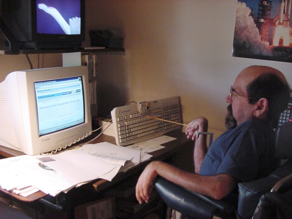
Over the years my disability has progressed. I used to have pretty good use of my hands so I could type on the computer, handle books and papers, even feed myself. I lost most of that in my early twenties. When I could no longer type on a keyboard using my hands I discovered an alternative way to type. I would prop up the computer keyboard on an easel so that the keys were facing me. I used a very long pencil or dowel rod in my right hand, put my elbow up on the armrest or control box, and I would poke at the keys. In the early days of 8-bit computers I would wire in in a couple of extra pushbuttons on the end of a long wire connected to the Shift and Control keys. I would hold those buttons in my left hand. By the time we got to MS-DOS and later Windows they had a built-in feature called “sticky keys”. Many people think that’s what you get from watching too much Internet porn but this is something different. It is a software driver that turns your Shift, Control and Alt keys into toggle keys. For example you push shift and the next key that you type will be shifted. If you push shift twice it holds the shift key down. Everything remains shifted until you hit it again to unlock it. Here is an old photo of me typing on the keyboard this way.
Me checking my stock portfolio using stick it keyboard on easel. Circa 2000
The photo shows a keyboard that was very near and dear to me. It was made by Gateway Computers and was called the “Gateway Any-Key 124 keyboard”. It had 2 sets of function keys, the traditional ones across the top and an identical set down the left side. It also had a special built in hardware keyboard remapping function. You could reprogram any of the 124 keys to send any remapped keypress that you wanted. It also would allow you to create macros so that one keypress would generate a string of multiple keystrokes. Because it was difficult for me to reach the arrow keys way off to the right side of the keyboard, I reprogrammed the top row of function keys into arrow keys. If I needed a function key I would use the ones down the left side of the keyboard.
You will also notice in the photo just above the keys is a mini trackball. It was the only way that I could operate the mouse. That particular model was small enough that it was handy to just mount on the keyboard with some Velcro. I could poke at it with my stick to operate it. The great thing about that particular model was that it included not only a right-click and a left-click button but it included a drag button. It was sort of like “sticky keys” for mouse buttons. You would toggle it off and on if you needed to drag. It would not right-click drag but you rarely have to do that. The problem with that particular trackball was it would wear out eventually. In the end I ended up buying three or four of them at once for about $50 each and keeping them in my closet just in case. The original Gateway keyboard had a 9 pin D serial connector. I was able to later purchase them with a round PS/2 style serial connector but they never did make one with USB. Fortunately I found some serial to USB adapter devices and was able to continue to do use this keyboard many years beyond its normal life expectancy.
When using a laptop, sometimes I was able to prop up the entire laptop on an easel so that the keys were facing me. I had to be careful when purchasing a new laptop because some of them do not allow the display to open a full 180°. Had I tried to prop up one of those, the display would’ve been facing the floor not to mention how difficult it would be to keep it on the easel. Even when I did put it up on the easel, it was very precarious. Eventually I started using the special Gateway keyboard on the laptop as well by just plugging it into the serial port or USB port with adapter later on. Because the keyboard had been discontinued and I was worried it might break, I even stocked up on those by purchasing a spare on eBay. I see here that they are still being sold on eBay. I still have a couple of them in the closet today. Maybe I should get rid of the old keyboards and make some money.
Vintage Gateway 2000 programmable 124 key keyboard available on eBay.
Enter the Dragon
At some point I supplemented all of this by using speech recognition software. I began using Dragon NaturallySpeaking when it was at version 7. I don’t remember what year that was. The current version is 14. Typically I would use my stick for most of what I did but if I had something long to type like a long email or a blog entry I would use the dictation. I didn’t realize that over a period of a couple of years I began using the Dragon more and more and would use the stick less. I recall one weekend we went to the cabin at Cordry Lake and although I had packed my laptop and extra keyboard, I had forgotten to pack the easel to stand up keyboard. So I had to just use Dragon alone the entire weekend. I was surprised to realize I didn’t really miss using the keyboard and trackball. It was soon after that that I resigned himself to using speech recognition exclusively.
Initially the stick in my hand was only used for typing. When I wasn’t at the computer typing on something, I would let go of the stick and leave it somewhere by the computer. Then one day back in the late 1980s as I was driving my wheelchair into my office, my hand slipped off of the joystick of the wheelchair and I crashed into a bookcase. Over the days that followed I begin to discover my arm had weakened to the point where I could no longer keep it steady on the joystick. After a little experimenting, I came up with a system where I would put the stick in my mouth. I would also hold that in my hand and the joystick as well. The mouth stick would steady my hand on the joystick of the wheelchair. Here is my typical driving position.
My typical driving position using the stick in my mouth to steady my hand on the wheelchair joystick. June 2015.
Can’t Touch This
Eventually I expanded my remote bracket on the wheelchair to make room for an iPod touch. If you’re not familiar with it, the iPod touch is sort of like an iPhone without the phone part. It plays music, video, games, and does Wi-Fi Internet access. I started out with the iPod touch model 1 shortly after it came out. The problem was the stick that I was using was a wooden dowel rod with a glob of silicone rubber on the tip so that it would not slip. Even if I turn the stick around and use the wood end, the iPod uses a capacitive touch system. The wooden stick would not activate it. I needed something metallic. After much experimenting I discovered that the metallic piece had to be a reasonable diameter rather than a sharp point. For example we tried just touching a key or a metal knitting needle but that didn’t work. It had to be flat and make flat contact with the screen. That was a problem because as you reach to the top or the bottom of the screen, the stick makes contact at a different angle. So we had to come up with something flexible.
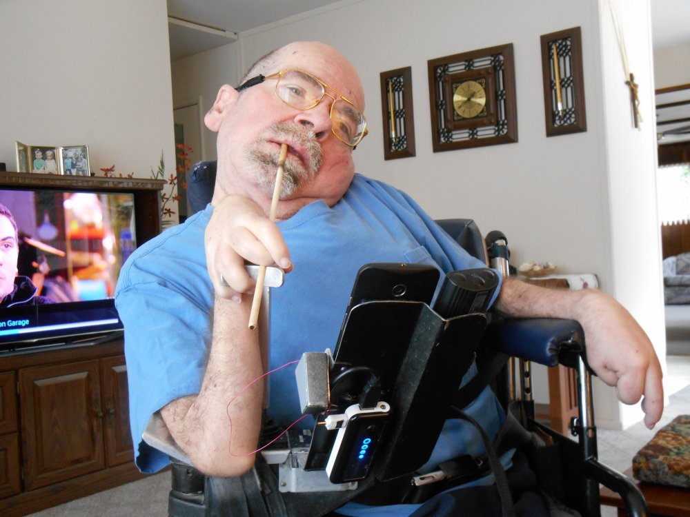
We finally came up with a piece of foam rubber with a hole in it so that you could put the stick into it. On the front of it we glued a small flat piece of metal. I would’ve thought that would be sufficient but it still wasn’t enough electrical capacitance. We attached a very thin ground wire to the metal tip and it worked fine. Having a wire attached to it also had other positive effects. For one if I dropped it, it didn’t go anywhere because it was tethered to the bracket. Also I can hold on to the wire in my right hand to steady the stick as I drag across the touch screen. Here is a photo of me using the stick to operate an android phone that later replaced the iPod touch. If you look closely you can see the thin red ground wire that I’m holding my hand.
Operating a smartphone and TV remote using a stick in my mouth.
We built a little receptacle on the side of the mounting bracket to hold the tip when I wasn’t using it as seen in this photo.
Small receptacle on the side of the mounting bracket holds the foam rubber tip when not in use.
Years ago I had upgraded the iPod touch version 1 to a version 4 but eventually it became obsolete. It would not run the latest version of iOS. Although there was an iPod version 5, the iPhone was already up to version 6 and I knew the minute I bought an iPod version 5 they would come out with 6. I waited and waited for various Apple product announcements. All of the rumor websites kept predicting that an iPod 6 was coming soon but it still hasn’t. A Google search on the phrase “android alternative to iPod touch” led to several articles suggested purchasing a cheap unlocked android phone. If you did not activate it, you could still use it for apps, Wi-Fi, games, music video etc. So that’s when I did. The image above shows the Motorola Moto G second-generation that I purchased. It is unlocked GSM phone which runs the latest version of android. It only cost about $180 and was a really good deal. I wasn’t sure I really needed a phone but once I was to the point where I couldn’t drive my wheelchair anymore, I could not drive up to get to the land line speakerphone that I usually use. I ended up activating it after all. I got a really cheap pay-as-you-go plan from ting.com that is costing me $12-$15 per month.
One of the problems with the android phone is it is larger than the old iPod touch. That means that as I reach from the top to the bottom of the screen, the angle of the stick varies more. It was more difficult to get a little flat metal tip to keep in contact with the surface. I came up with an interesting adaptation to solve that problem. We took a small piece of conductive foam such as used to protect IC chips from static electricity. We cut it in a little rounded hemispherical shape and glued it on to the little metal plate on the end of the stick. So no matter what angle I used, there was still sufficient surface touching the screen. Here is a photo comparing the size of the new android phone on the left and the iPod touch 4 on the right.
My comparatively tiny iPod touch 4 next to my newer Moto G android phone.
Here is a close-up showing the flat tip on the right that I used for the iPod and the one on the left is the new rounded tip use for the android phone.
That whole system worked really well for several years. It got me through hundreds of levels of Angry Birds and above level 1000 on Candy Crush as well as allowed me to look up countless facts on IMDb, post to Facebook, and check the weather radar anytime I felt like it.
I.R. An Expert
The stick isn’t the only piece of adaptive technology relevant to the story. A lot of what I do is assisted by infrared remote control such as the ones used by TV, cable, DVD etc. It was about three years ago that I got back into tinkering with electronics when I purchased my first Arduino microcontroller. I became interested in infrared remote controls and that led to the building of the TV/cable remote that I use in bed. The whole journey was documented elsewhere in this blog. I came up with another use for the Arduino when they introduced the Arduino Leonardo model. It is capable of emulating a mouse or keyboard when plugged into the USB port on the computer. So I built a little box that would pick up signals from my TV remote and it would create mouse movements as well as some keystrokes most specifically the arrow keys. I could switch back and forth between mouse mode and keyboard mode. Because I don’t have a cable box in my office, I use various codes from the cable box to control this device. However when I built another one for my laptop that I often use in the bedroom, I had to pick a different set of codes for that one so that it didn’t change channels. The one for the laptop used code from my Blu-ray player. I never use the laptop in the living room while watching Blu-ray so that was okay.
While Dragon dictation software does have mouse controls, they are not very flexible. For example you cannot use the mouse scroll wheel, it is difficult to shift drag and you cannot right-click drag at all. But pushing the TV remote with my stick, I can do all of that and more with the Arduino Leonardo and an IR receiver.
My infrared remotes are based on a library of code written by a guy named Ken Shirriff which I later rewrote to make a little more flexible. I published the code on GitHub and on this blog. My version has been so popular, I’m considered somewhat of an expert on IR remotes. It has been really satisfying to get emails from other people who have built their own IR remotes for their elderly or disabled friends and family. One guy build a remote for his nearly blind grandfather using my code. His version has very large pushbuttons and plays back soundbites when you push the button. It includes specialized buttons that automatically jump to some of his grandfather’s favorite channels such as news or sports. The guy just recorded his own voice to play back but I think it would’ve been better to have James Earl Jones say “THIS is CNN!” or the ESPN Sports Center jingle “Duh da dant, duh da dant”.
RIP The Stick
It’s kind of interesting that the stick saved me from two separate situations where I was very emotional over lost ability. When I couldn’t type anymore using my hands I thought it meant the end of using the computer altogether. The stick let me keep typing. Then when I couldn’t drive my wheelchair anymore, the stick let me keep driving. It also had other uses such as pushing TV remote buttons and operating an iPod or touchscreen smartphone. Unfortunately I met another one of those crossroads moments where I can’t do what I used to do. The stick is not going to bail me out. In fact because I could no longer get the stick into position that I needed, I’m not able to use it to operate the remote, the phone, or to assist me with driving. Here’s a brief video that shows how difficult it was for me recently to be able to get the stick into position.
That video was recorded back in June 2015. As I write this in January 2016 things have gotten worse. For the past couple of months I haven’t driven my wheelchair all. I couldn’t get the stick into position without help, so anytime I wanted to go somewhere, dad would have to get into position and even once I was there sometimes it was too difficult to drive. So in recent weeks he just pushes me everywhere. The new wheelchair I’ll be getting should resolve some of that. You can see other videos and blog entries about my quest to get new wheelchair.
Arduino to the Rescue
Now that I am no longer able to use the stick, I had to come up with something else. I had been anticipating this problem for many years especially when it came to using the TV remote. After using my specialized Arduino powered remote in bed with just a few pushbuttons, I realized it was much easier to use than pushing the buttons with my stick while sitting in the wheelchair. This latest remote that I purchased has very tiny buttons and unless you get the tip of the stick in exactly the right place they would not push. So over two years ago, I began working on building an Arduino powered TV remote to replace my usual universal remote.
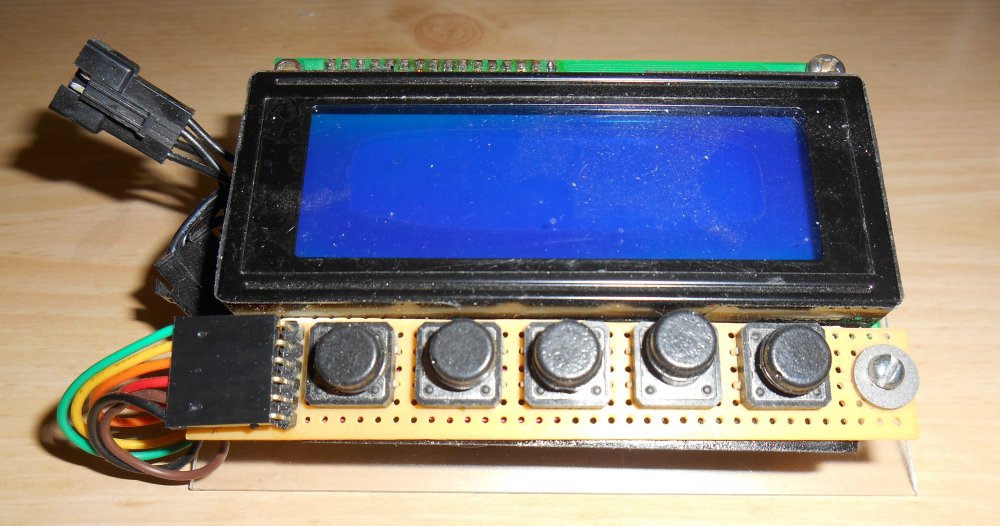
I started out with an Arduino Leonardo and a 4 x 20 character LCD screen. This was going to be the ultimate remote that not only would control the TV and the computer mouse, it might also be used as a wireless infrared keyboard. That’s why I needed the bigger display. I decided I would put four or five pushbuttons on it to scroll through the menus. I would still using my mouth stick but I would have the options of attaching micro switches that I would hold in my hand. We actually built an early prototype of the device and it was pretty cool but it was a little bit impractical. It was rather large and heavy to be mounted on bracket that I had been using. I wasn’t sure what I was going to do to provide power to it. Also the various types of pushbuttons that I tried worked very well. If I used micro switches on the end of a wire, I had to put my arm in an awkward position in order to be able to use them. This particular device didn’t go completely unused. I programmed it with special codes for a toy helicopter that used in infrared remote as well as a toy dinosaur. I’ve already documented those projects in other blog posts and videos. I never did get around to using it as a TV remote because I couldn’t come up with the right buttons. Also I didn’t really need it, I could still pushbuttons with the mouth stick. Keep in mind this project started almost 3 years ago when I was in better shape. Here’s a photo of the prototype was a large 4 x 20 LCD display that I never did get fully working.
The Leonardo-based IR remote with 20×4 character LCD. I never finished it.
Here are the 5 micro switches connected to the Arduino Leonardo remote that I could have used as an alternative to the pushbuttons on the device itself. I used these switches to control the helicopter and the toy dinosaur. It turns out that 5 switches were too many. I could not comfortably hold them and I could not hold them if my arm was in a position where I could drive the wheelchair with the joystick. Now that I’m no longer using my hand for the joystick, I found a position where I could comfortably hold 3 of these switches with a little adaptation which I will show you later.
Internet of Things in the Interim
Pinoccio Wi-Fi Development Board
In the interim, I found other ways to control my TVs but this time over the Internet. Using the old Pinoccio Wi-Fi module and a webpage I was able to control the living room cable box from my adjacent office by clicking on a webpage. I have an HDMI splitter connected to the living room cable box. One output goes to the living room TV where my dad watches. The other output goes to a very long HDMI cable that goes through the wall into a TV in my office. There I can watch the same thing as dad is watching the living room. Of course he falls asleep in the recliner when doesn’t fast-forward through the commercials. Being able to control the living room cable box remotely is very useful. I also set up a similar system between the cable box/DVR in my bedroom and ran it into the office although I use RF coaxial cable for that link which makes it standard definition only. Still it’s very useful. I also made the webpage sensitive to keyboard presses which meant that I could use my voice control to operate it. For example if I would say “Press P” using Dragon dictation, the webpage would push the play button. The arrow keys were especially useful when browsing through the on-screen guide. I could simply speak the Dragon command “move right 6” or “page down” and it would scroll around the on-screen program guide.
Arduino Yun
The Pinoccio platform was unreliable and eventually discontinued. You can read about my love/hate relationship with that elsewhere. I replaced it with the Arduino Yun which not only made it a Wi-Fi compatible Arduino platform but it had a built in advanced processor running a version of Linux that could serve the webpages rather than hosting them on my PC. The Arduino Yun can be reprogrammed by Wi-Fi which is very useful. I can upgrade the software anytime I want. The unit in the living room is stuck underneath an end table next to my dad’s chair. The one in my bedroom is up on a bookshelf. In recent months as I’ve lost the ability to use my regular remote and stick I even added a third Arduino Yun in the office which is only used to turn the office TV off and on and control the volume. Each has its own webpage and creates its own IR codes specific to the devices in that room. I also have webpage control to a Kodi/XBMC media server running on raspberry pi. So I can control 2 different cable boxes, three different televisions, and three different raspberry pi media players all using webpages designed to be compatible with voice control.
Chris helped Christopher. Christopher helps Chris.
I still miss being able to push remote buttons. Once I realized I really do need a cell phone for safety purposes since occasionally dad leaves me alone while doing errands, I had to come up with a way to control the phone again now that I could no longer use my stick to operate the android phone. I could give up playing Angry Birds. You can play Candy Crush on a Facebook webpage. But I really need the phone. Thanks to a young man named Christopher Hills who lives in Australia, I discovered that my move from iOS to android was a mistake. He has cerebral palsy but he doesn’t let it stop him from pursuing his hobby and vocation of making videos. He is somewhat of an expert in adaptive technology. He posted a YouTube video embedded below in which he describes new accessibility features in iOS version 9. It allows you to use one or more pushbuttons to access nearly every function of the phone. Of course it also works for iPad tablets. The pushbuttons are connected to the phone or tablet over a Bluetooth connection.
Seeing that video was a very emotional experience for me. For one it was the realization that I could continue to use a smart phone after all. But he also reminded me of my late friend Christopher Lee. He was a friend who had very severe cerebral palsy. I had built an accessible computer for him back in the early 1980s. My late friend could not push a button but he could make a clicking sound with his tongue. Of course there was no speech recognition back in those days because of eight bit computer just wasn’t powerful enough to do it. I will write a whole other series of blog posts about my friendship with him and the things that we went through to get him computer access. It’s amazing that 30 years ago Chris Young was building accessible computer for a guy with cerebral palsy named Christopher Lee. Now a guy named Christopher Hills with cerebral palsy extremely similar to the severity of my friend Christopher Lee is demonstrating to me how I can continue to access a smartphone. It all came full circle. Here’s a link to the video demonstrating the switch control features of iOS 9.
Just-In-Time Technology
It’s a bit creepy that the technology that I need, has been developing just in time for me to use it. For example the mouse control via Dragon dictation software is usable but awkward. Once I got into Arduino I wanted to find a way to emulate a mouse or keyboard. While I was investigating various hard ways to do that, they released the new Arduino Leonardo which made it incredibly easy. Just as the Pinoccio platform was shutting down I discovered the Arduino Yun which in the long run was a better solution. And just as I was losing the ability to use a smart phone, iOS 9 was being released with unprecedented powerful switch control features. Then another “just-in-time” technology came along. The electronic supplier that I use, Adafruit Industries, is a phenomenal organization designing and selling maker products around the world. They are where I buy all of my electronic parts and I show off my projects on their weekly video chat “show-and-tell”. They had recently begun slowing various modules for Bluetooth control. The new Bluetooth 4.0 also known as Bluetooth Low Energy or BLE makes it very easy to build gadgets that communicate with computers, tablets, or smart phones via Bluetooth. That was exactly what I needed if I was going to use wireless switch control.
Adaptive equipment suppliers market Bluetooth devices especially made for switch and/or joystick control at a cost of up to $500. There was another model for about $150 that wasn’t nearly as capable but would work with a couple of push buttons. However I could purchase a handful of parts from Adafruit and I could build one for under $75. By building it myself I could customize the software however I wanted. I could incorporate whatever other functions I wanted besides the iOS switch control including making it an infrared remote TV, cable and mouse control.
Step-by-step all of the technology that I needed was appearing exactly when I needed it. They say a coincidence is when God creates a miracle and nobody notices. I was noticing things falling into place.
Goodbye Android… Back to iOS
There was switch control the older versions of iOS however my old iPod touch only worked up to iOS 5 or 6 I forget which. Those earlier versions of switch control left a lot to be desired. Until I saw that Christopher Hills video, I had no idea how capable it had become. Latest android version also introduced switch control but it wasn’t nearly as powerful or useful as iOS 9. It was obvious I was going to have to switch back to iOS.
I recently purchased an iPad for my nephew that he needed for school. Before delivering it to him, I tinkered with it using an Adafruit Bluefruit Micro BLE module and prove that it could communicate with iOS 9. That startled the issue for me. Although it cost me a fortune, I purchased an unlocked iPhone 6. Really didn’t need the 6s or the 6 plus versions. I could still keep my cheap pay-as-you-go plan that’s costing me less than $15 per month. I very rarely am away from Wi-Fi so I don’t need to pay $40 per month for unlimited data. My dad retired his old flip phone and inherited my android phone. He’s having a lot of fun with it learning how to use smartphone features he’s never had before.
Finally the Ultimate Remote “The IRBLE”
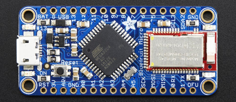
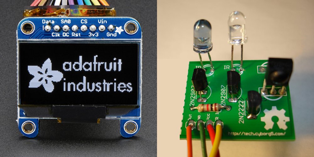
Since I was going to be building an electronic device to operate the iPhone, it was time to also incorporate TV/cable remote capability as well. Technology had advanced that things were smaller and more capable than when I first started building the big display Arduino Leonardo remote three years ago. The Arduino Micro BLE has the same ATmega 32u4 processor as the Leonardo. Additionally it has Bluetooth and it is only slightly larger than a USB thumb drive. Instead of the huge LCD display that only display 4 lines of 20 characters, Adafruit now sells an OLED graphic display that is only 1.3 inches across but has 128 x 64 pixels of resolution. Because I no longer had to keep my arm in a particular position to drive the wheelchair, I could place my arm in a position that made it easy to hold the micro switches to activate the device. I now have a 3-D printer which allowed me to make a little gadget that attaches to the micro switches that makes it easier to position them in my hand securely. The only remaining problem was how to get power to device. I had solved that problem a few months ago by designing the Printy Boost battery pack which uses a LiPoly battery, an Adafruit charging module and a 3-D printed case of my own design. Click here to see the tutorial I wrote for the Adafruit Learning System showing you have to make your own Printy Boost battery pack. I had already been using this battery pack to supplement on my android or iPhone. I just needed to run a little cable from the battery pack over to the new remote.
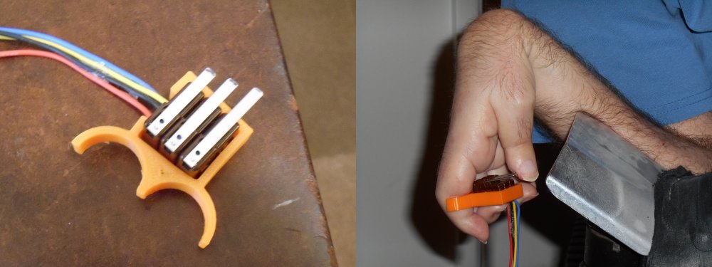
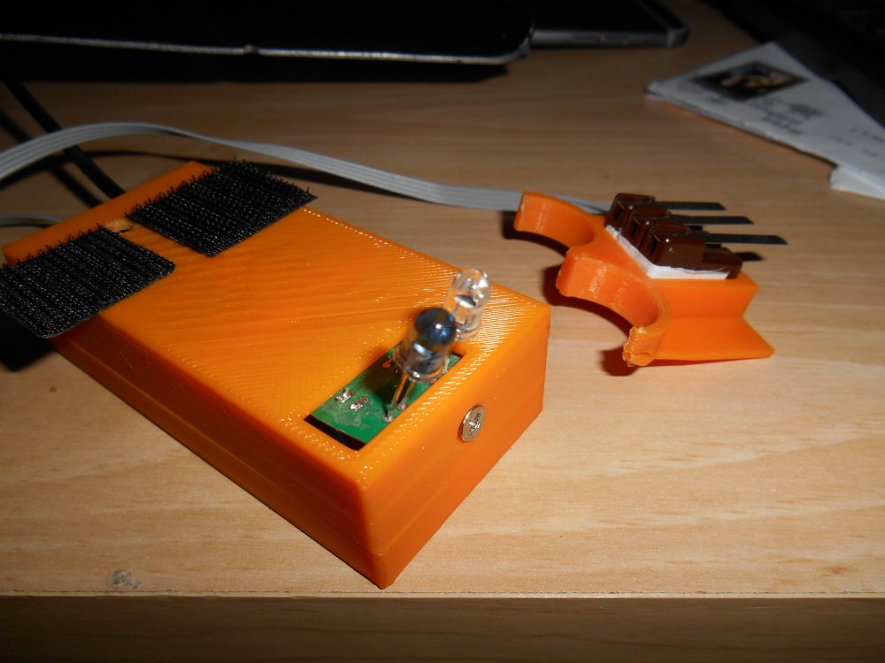
I have decided to call it “IRBLE” (pronounced the same as herbal) which is an combination of IR for infrared and BLE for Bluetooth Energy. Here are a series of photos of the project.
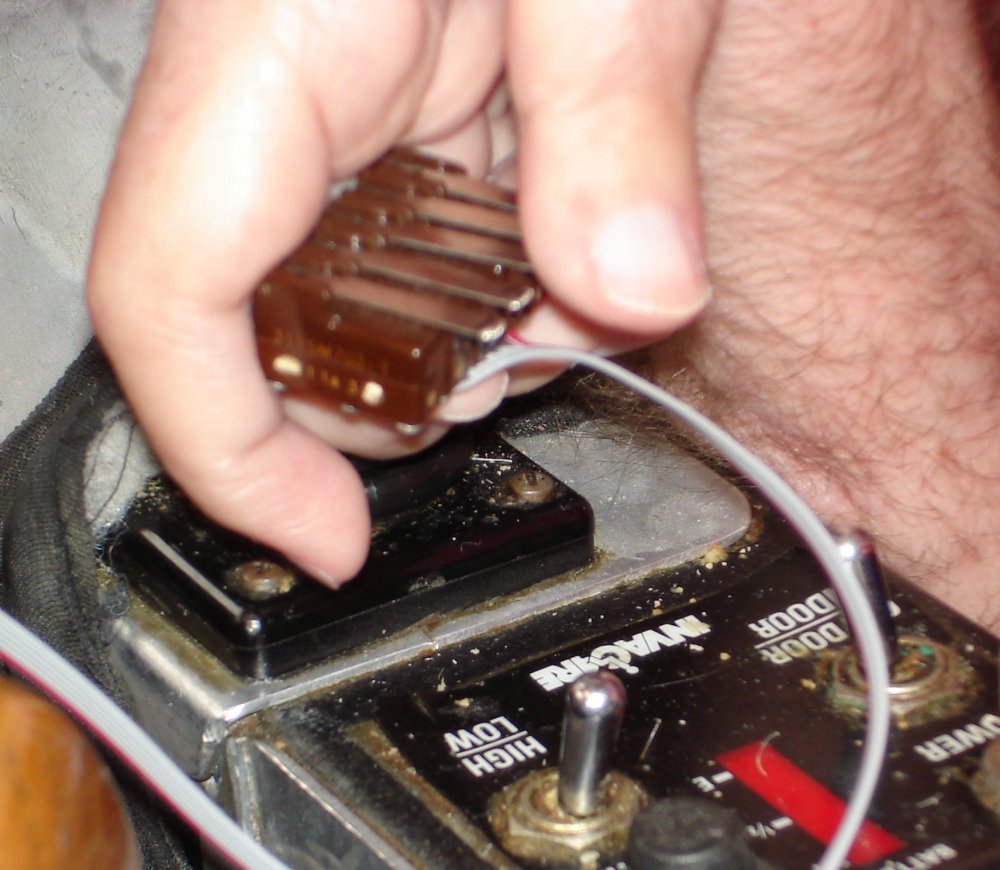
This is me holding three micro switches in my right hand. The orange plastic is a 3-D printed adapter that lets me hold the buttons in the proper orientation.
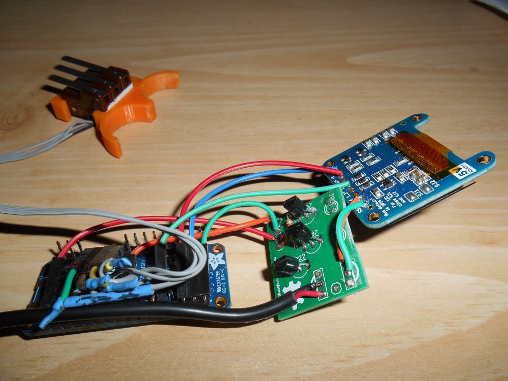
Here are the Adafruit Micro BLE board, the Adafruit 1.3 inch OLED, and my custom-designed infrared output board that I use for all my projects.
The Adafruit Micro BLE measures about 2″ long.
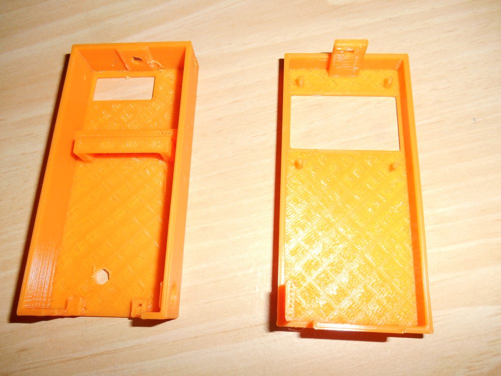
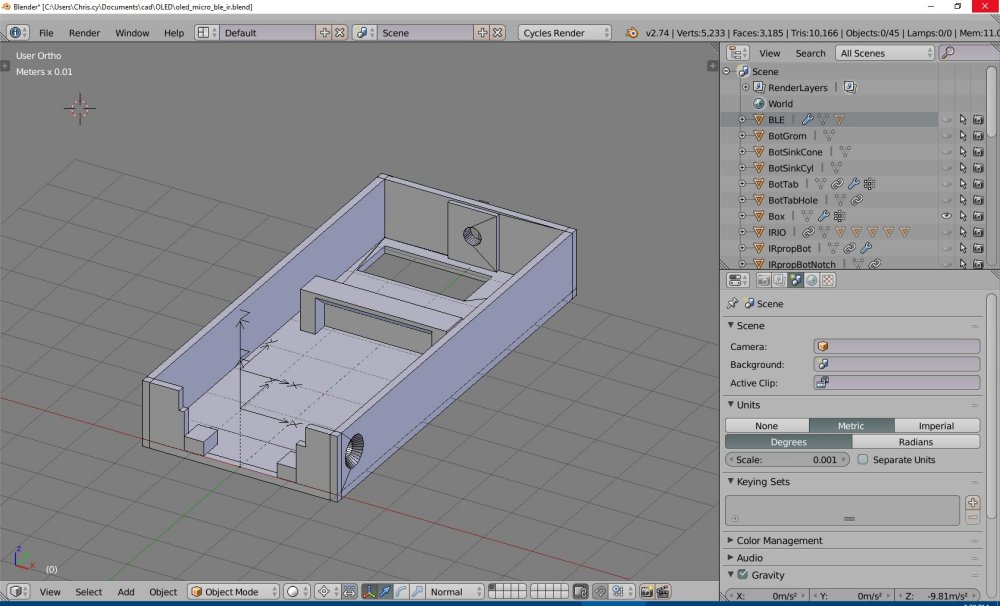
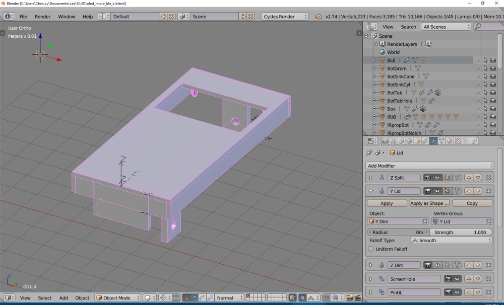
Here is the 3-D printed case will I made for the new device. Below that are some screen grabs from Blender 3-D when I designed the box.
Here’s the thing all wired up. It looks a mess but it works. Thanks to dad and his excellent wiring skills.
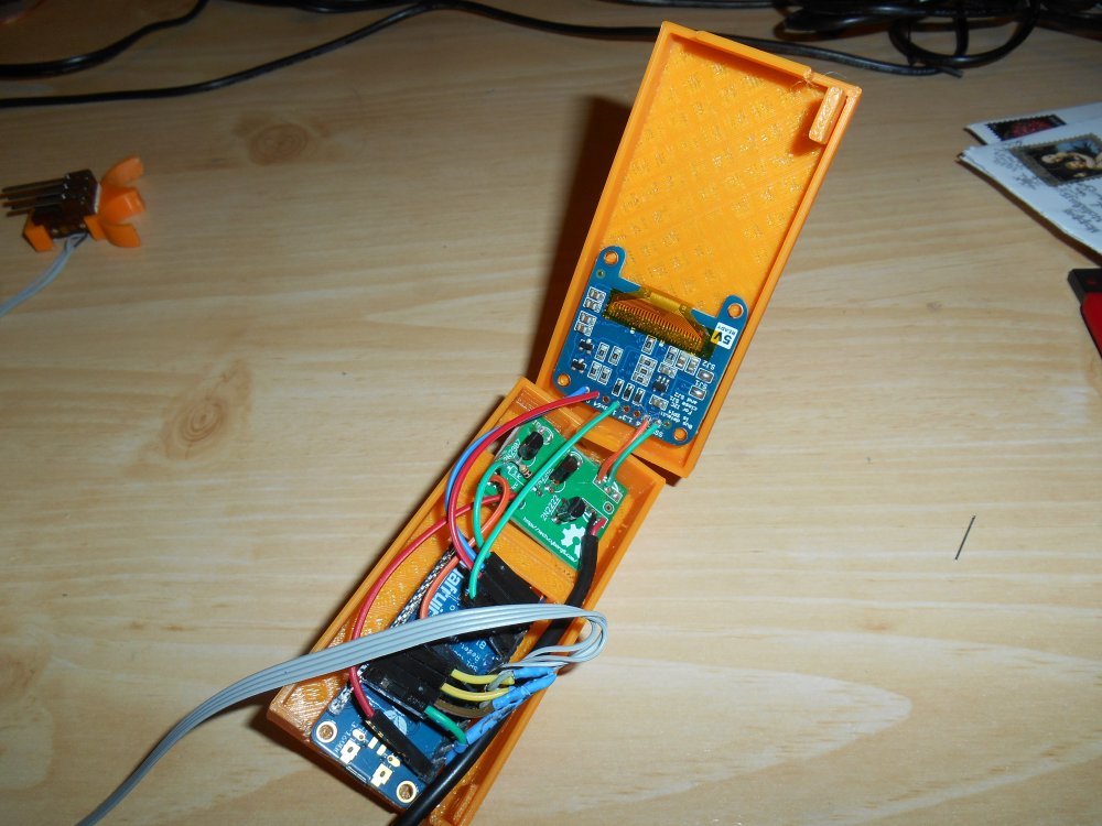
Here are the parts in the case.
Here is the backside of the assembled device showing the infrared LEDs protruding out of the case. These transmit the signals to the TV or cable box.
You can also see the Velcro tabs is to attach it to my bracket on the wheelchair. Between the tabs is a tiny hole which we drilled in the back of the case so I could reach the reset button. A couple of times during the programming I had a glitch and nearly bricked the device. Fortunately if you hit the reset button at just the right moment and initiate and upload it will work again. I was worried I would not be able to recover it After one of the glitches. Believe it or not even though this board was only introduced a few months ago, it has already been replaced by a new model. Adafruit has a new line of development boards called “Feather” that come in a variety of configurations. If I had ruined my board I already had purchased one of the newer Feather models but I would’ve had to redesign the wiring harness and the 3-D printed enclosure. Fortunately I was able to recover it.
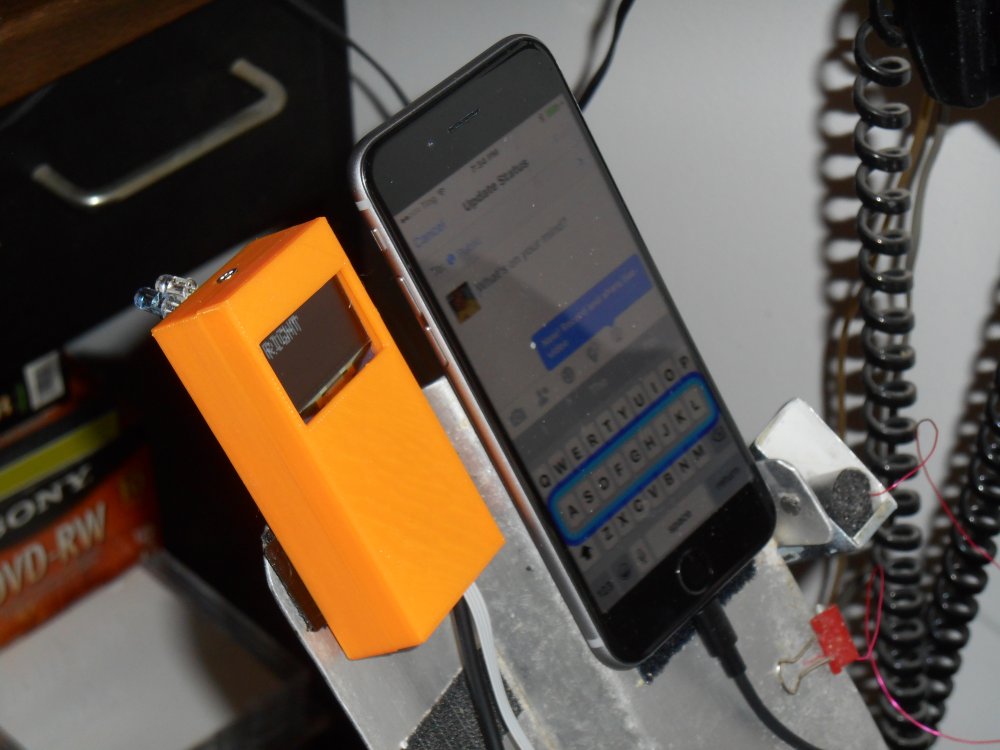
Finally here is the final product mounted on my bracket next to my iPhone 6.
You can see on the side of the mounting practice holding the old capacitive touch foam rubber tip for my stick. I probably will never use it again but there is one final thing for which I might use the stick. When playing Candy Crush on a timed level I cannot work the mouse with my voice control or IR remote quickly enough to finish the level. I can only do those levels with the stick in my mouth. But other than that, I won’t be needing the stick anymore.
The TV in my living room, bedroom, and office are all Samsung and use the same codes even though they are different models. The cable box in my bedroom in the living room uses the same codes. In addition to being able to control all of that, and the mouse and arrow keys on my desktop PC, also programmed in the kitchen TV and the surroundsound amplifier in the living room. As I’m writing this, I still need to program in codes for my Blu-ray player. I’m a little bit worried I might run out of space on the Arduino. It is only has 2K of RAM memory and 32 K flash memory. I only have about 150 bytes of RAM remaining and I’ve used 94% of the flash memory. Fortunately Adafruit also has a Feather board that uses ARM Cortex M0 processor. https://www.adafruit.com/products/2995
It runs at 48 MHz, as 256 K of flash memory, and 32 K of RAM memory. I would have to rewrite my infrared code library but I intend to do that anyway.
Among the things I can do besides make phone calls and run most apps, I have an app that gives me remote control of the Kodi media players on my raspberry pi. Of course I could modify the design of the remote to use a Wi-Fi add-on and control the raspberry pi easier than through the phone. Adafruit does not yet make more than has both Wi-Fi and Bluetooth but my guess is by the time I got around that, they will have one. Possibly a Wi-Fi add-on for the Bluetooth board or a Bluetooth add-on for a Wi-Fi board. For now I got a remote do absolutely everything that I need it to do.
We can finally retire my last stick.
Epilog: Recently I was hospitalized and had to be put on a ventilator. The only way I could effectively communicate with doctors and nurses was to use this Bluetooth device to type messages into the notepad application on my iPhone. You can read a multipart blog about my hospital adventure titled “Pray That They Listen to the Man with No Voice“. Also I’ve written a tutorial for the Adafruit Learning System describing how to build a Bluetooth device for iOS switch control. You can read it here.
One more item… After over a year of faithful service my Ultimate Remote gave up the ghost. Here is an article about the replacement unit that I built.
I couldn’t help myself. As a birthday present to myself for my 60th birthday, I bought myself a 3-D printer. Is a Printrbot Metal Plus with a 10 x 10 x 10 build area. It will print PLA or ABS plastic. It has a heated printer bed and a 0.4 mm extruder nozzle.
The first thing you do when you set up the printer is you print a little square piece of plastic about 10 mm on the side and 3 mm thick. Look at the bottom surface of this part to see how it compares with one that was done at the factory. Unfortunately I had tinkered with some settings and did something wrong and on the first attempt to print, the printhead crashed into the print plate and started tearing up the Kapton heat resistant tape that covers the print bed. We peeled it off, salvaged part of the tape that was not damaged, and reapplied it in a strap across the middle. I ordered a new piece of tape that would cover the entire surface but it didn’t get here until several days later and I didn’t get around to applying it until weeks later. I got by because the objects I was printing would still fit on the smaller piece of tape.
For my first real prints, I downloaded some objects from a variety of websites such as Adafruit Learning System and Thingiverse. The first thing that I printed was a little bust of Yoda. Among the varieties of plastic I purchased was a color called slime green. I thought it would look good for Yoda. The original design would’ve taken over two hours to print and I want to see something quicker than that so I scaled it down and it only took a little over an hour.
Here is a YouTube video showing the print. It was posted on July 7, 2015
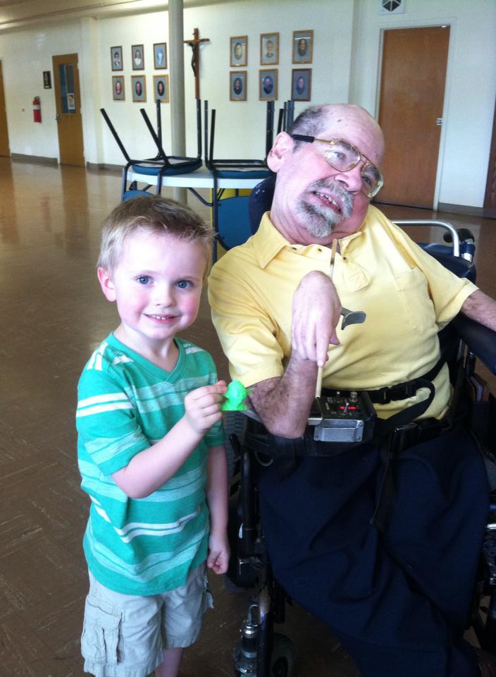
A few days later on July 12 at my 60th birthday party, I was showing off some of the objects I had printed. My cousin Angie told me that her little boy Jonathan was a huge Star Wars fan. I decided that he would give Yoda a good home so I gave him my inaugural 3-D printed object. Here is a photo from the party of me, Jonathan, and Yoda.
Note: although I uploaded this video on July 7, and I shared it on Facebook and Google Plus, I didn’t get around to writing this blog entry until mid-September. However to keep the sequence of events straight in my blog, I have predated this to July 13 which is the first day I could’ve actually written it if I had done so in a timely manner.
I’m a tiny bit sad to report the death of Pinoccio. Note that the missing “H” is deliberate. I’m not talking about Pinocchio the beloved character from children’s literature. I’m talking about “Pinoccio” (without the “H”) open-source semi-Arduino-compatible hardware and software platform. Actually to say that I’m reporting it is a bit of yesterday’s news. It was actually reported here in a blog post on their website dated March 30, 2015. The reason I didn’t see that blog post right away is that I had pretty much given up on the system several months earlier.
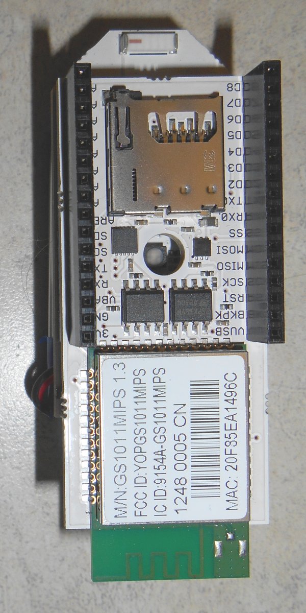
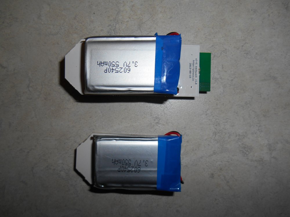
Here’s a bit of history… In late 2012 or early 2013 I became aware of this Indiegogo campaign titled “Pinoccio – A Complete Ecosystem Building of the Internet of Things” It was a small 1″ x 2″ Arduino compatible board using a chip similar to the one used by the Arduino Mega. This variety had a built in mesh radio such as used by the X-Bee system. It had a built-in LiPo battery, an RGB LED, a temperature sensor and a Wi-Fi backpack. You could connect to one of the units called a Lead Scout via Wi-Fi and then it would communicate to the other units over mesh radio which were known as Field Scouts. I quickly signed up at the $149 support level which would get me a Lead Scout and a Field Scout. Although the units were a bit pricey, if you added up what it would cost to buy an Arduino Mega, battery, charger circuit, X-Bee radio, and Wi-Fi module it seemed like a bargain at the time. They were seeking $60,000 in funding and end up raising over $105,000. Put this in proper context note that this was several months before Spark Core appeared on Kickstarter. Note that Spark Core has recently rebranded as Particle.io.
Had Pinoccio made its original delivery date of July 2013 they would’ve beaten everyone to market and would’ve been a major player in the Internet of Things movement. There were plans for a smaller version without the battery and sensors that would’ve been easier to embed into production products. There were plans for a variety of backpacks or shields including the one I was most anxious to see… infrared LED and receiver. My goal was to use it to create an Internet capable IR remote. I wanted to create an inexpensive alternative to the RedEye IR Remote from ThinkFlood. And it was a good thing I was planning such because ThinkFlood was shutting down as seen here.
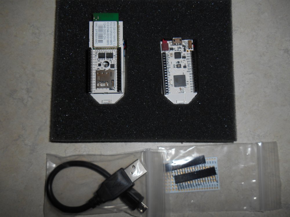
My Pinoccho boards upon arrival.
The folks from Pinoccio quickly learned the hard lessons of crowd sourced funding. Lesson number one is inevitably “If you’ve got a great idea it’s easier to raise money then it is to bring a product to market.” I won’t bother to recount the litany of things that caused multiple delays but the bottom line is that backers did not get their units until April 2014 a full 10 months past the initial estimated delivery. The reasons were the usual things: finding suppliers, finding someone to make the boards, setting up the business itself. It seemed that the main reason/excuse for delays was that “We want to get the software right.” Here is my blog post which gave my initial positive reaction to the devices when they finally arrived.
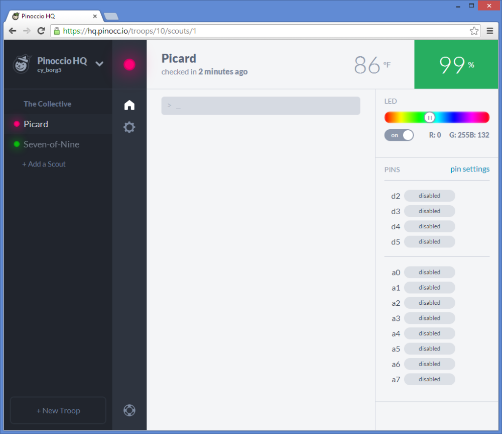
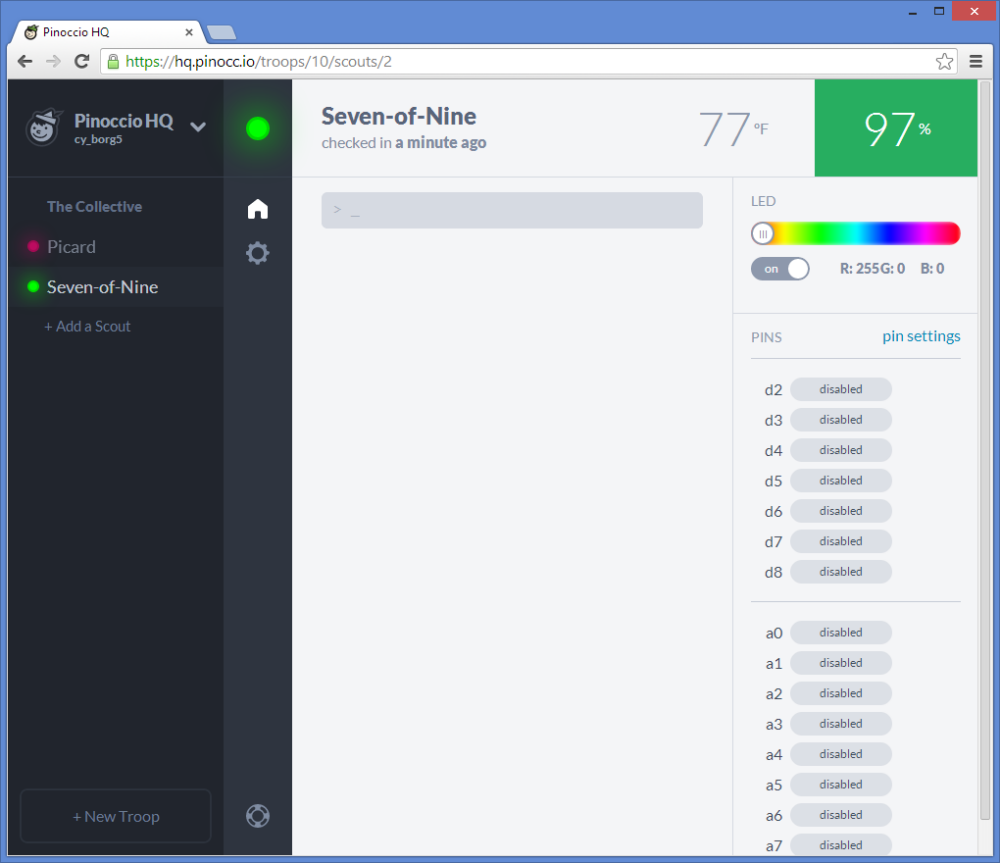
The software that we waited so long to finally get was indeed quite extensive. There was an Internet portal called hq.pinocc.io that allowed you to do many things without even writing any code. And it included an extensive script language that you could write small programs directly from the HQ application without having to use the Arduino IDE or do any C++ coding. They wanted you to be able to plug the thing in and do something with it right away. That ability is one of the key things that led to the success of the original Arduino. With a built in RGB LED and temperature sensor, you could do more than just blank the LED on pin 13 like you can with Arduino out-of-the-box.
However if you wanted to write your own applications, the learning curve at least for me was very steep. I had no experience in connecting devices to the web. I did know quite a bit of JavaScript programming, CSS, and DOM HTML programming which was useful. I had a little bit of experience with PHP however that did not apply in this case. What I did not have any idea how to do what is called “asynchronous communication” with Web servers.
I was taught as a programmer from day one that execution of a program started at the top of the main module and went step-by-step through the module sequentially unless modified by the if/then/else or some sort of loop structure. But asynchronous coding is something significantly different. You make a request to a Web server and within that request, you send it the code that you want to execute when it finishes the job. That seems simple enough. I figured it would call the code when it was ready and then move on to the next step. But it doesn’t work that way. You move on to the next step immediately after making the request and you have no idea when it’s going to complete that request and invoke your callback function. I would make a request from the server for a piece of information. My callback function would tell the server where to put that information in my program. Then I would try to display that information on the webpage. But it was never there. When I would insert debugging code to see why it wasn’t there, it was there. It reminded me of the paranoid poem about the little man on the stair.
“Last night I saw on the stair
The little man who wasn’t there.
He wasn’t there again today.
Oh how I wish he’d go away.”
I was being haunted by the returned data that wasn’t there 🙂
What I didn’t understand was that this callback function wasn’t a normal subroutine where you call it, it executes, and when it returns you carry on. You have to carry on immediately after the request and you don’t know how long it’s going to take for the Web server to return your data. So you have to put something in the callback function that tells your main program “Hey he finally got what you asked for. You can use it now. It’s really here.”
When you are collecting several pieces of data in a row and you don’t want to proceed until you’ve got them all, the nested callback functions can get pretty hairy. It took me a long time to figure out what I was doing wrong. It also took a lot of patience on the part of the people from Pinoccio in their support forums to walk me through my inadequacies is particular area of programming. I owe them a tremendous debt of thanks. (Humorous note here… When I dictated the previous sentence using my dictation software, it misunderstood me and said “I/O them…”. How appropriate for a “.io” system). Anyway they were most gracious and patient with me.
I did my best to pay back their kindness. I blogged everything I could about the device. I showed it off on the Adafruit Google+ Hangout Show-and-Tell. I blogged about how to get around some SSL certificate problems that cropped up along the way. And I did my best to educate them in the hardware requirements necessary to make an infrared backpack for the Pinoccio system. And ultimately I did get a working Internet-of-Things infrared remote that I used to operate my TV and cable box.
My cable box is located in the living room but I have an HDMI cable that runs into my adjacent office so that I can watch the same thing my dad is watching and living room. I can get on a webpage in the office and control the cable box in the living room. I used it every day for several months and it was a real godsend. I succeeded in replacing my defunct and unsupported RedEye remote.
I included Pinoccio support in my next public release of my infrared library IRLib. I began cleaning up my asynchronous webpage code and preparing to publish it to share with the world everything I have learned so that the next novice who came along would have a clear and simple tutorial to follow I would not have to bother the people in the support forum to learn the things I have learned the hard way.
One of the things that bothered me about the entire system was that it was totally dependent upon the website hq.pinocc.io servers were maintained by the Pinoccio organization. On occasion, their server would crash and I would be stuck with a useless system. I asked them what do we do to remove that dependence. The old RedEye remote system was accessed directly to the local IP address of the device itself. It also included its own Web server in the device. In contrast the Pinoccio system required me to make my own webpage to control the device (as great as HQ was it wasn’t sufficient). That meant I had to install a Web server on my PC. I can only control the system from that PC unless I uploaded the webpage to cyborg5.com which I didn’t want to do. Setting up WampServer on my PC was much easier than I anticipated. That allowed me to host my controlling webpage with no problem.
Furthermore my webpage could not communicate with the device directly. It had to go through their servers. My controlling webpage went to a URL on their server and their server connected back to the device itself. The whole point of Pinoccio, for me at least, was to replace the defunct out of business RedEye Remote. What was I going to do if Pinoccio ever folded? They assured me that they were working on a system that would allow direct connections without going through their server system. And in the end they did so.. They developed a system where you could plug one Scout into a PC and have it communicate directly with the other Scouts using the mesh radio. You didn’t need the Wi-Fi at all. They called it a “Bridge Scout”. While that was of suited my purpose, still wouldn’t have given me all of the capabilities the device should have had. There supposedly is a way to set up one’s own server that would duplicate their part of the infrastructure. I believe them when they tell me that. However doing that myself would required another steep learning curve that I didn’t really feel like attempting. It would require more than I can get out of WampServer. It involved node.JS and a variety of other things that were beyond me.
Unfortunately somewhere along the way the device got a bit glitchy. There were constant software updates some of which I kept up with and some I did not. After not doing updates for several months, I finally decided to do an update in hopes of fixing the glitches. The end result was my device quit working altogether. I spent a couple of weeks presuming that the problem was an adverse interaction between my infrared code and their systems software. It involved going onto GitHub and figuring out which version of the software I had been using that was working somewhat well and then individually applying each and every update that had occurred over the period of several months. I finally found the patch that was causing my code to crash. In the end it was not an adverse reaction between my infrared code and their system. I was able to whittle it down to an example that did not include my IR code at all.
Somewhere in the midst of all this, I ended up “bricking” my lead scout. Somehow during a crash, the boot loader was overwritten. They talked me through a system wherein you could use one Scout as an ISP to restore the boot loader on a broken Scout. Initially that process did not work because I tried to do it with the Wi-Fi backpack still installed. Somewhere along the way while adding and removing the Wi-Fi backpack without disconnecting the power, I permanently damaged the Wi-Fi backpack. That meant that the so-called “Ecosystem for the Internet of Things” was no longer Internet capable. A replacement Wi-Fi backpack would cost $79. I was able to get the system running somewhat using the bridge Scout they described where you had to keep one unit plugged into a PC to communicate with another unit. However I had become frustrated with the whole thing and needed to get away from it for a while.
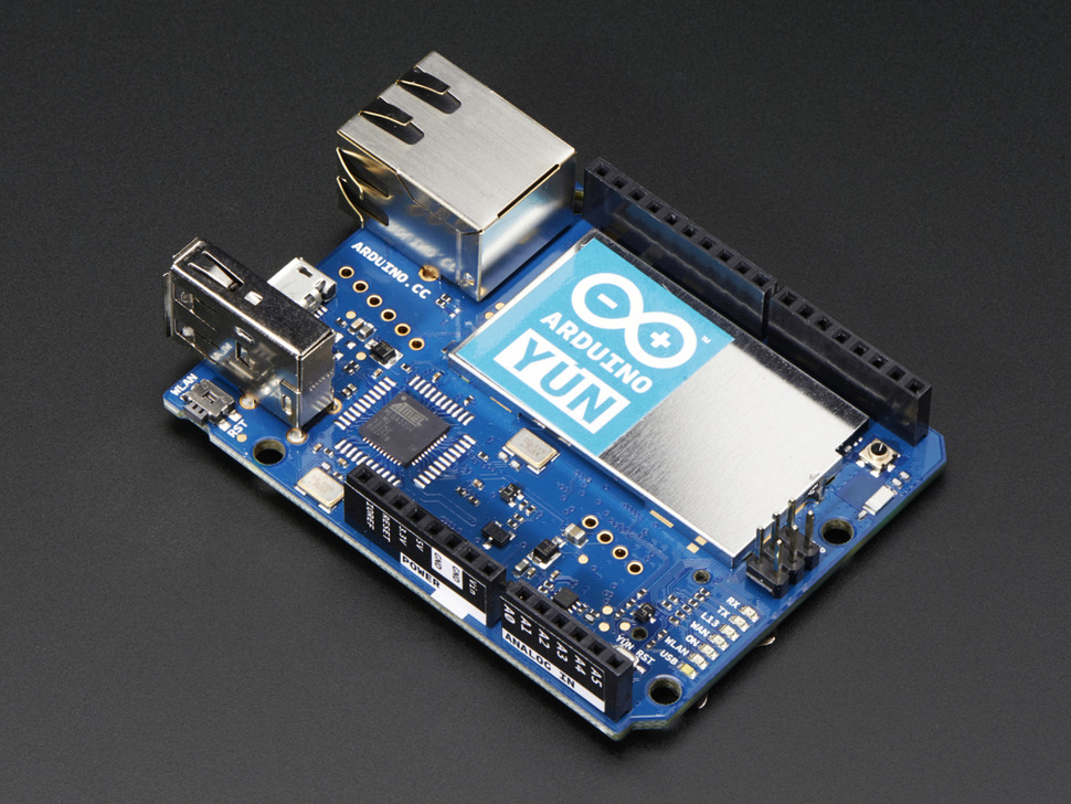
I ended up ordering an Arduino Yun from Adafruit.com. I immediately fell in love with the device. It consists of a powerful microprocessor running a minimal version of Linux and an Arduino Leonardo in one device. The communication between the Leonardo and the Linux was well defined and easy to use. The Linux portion did include its own Web server. You could also update the onboard Arduino sketch and the associated webpage using the latest Arduino IDE and do so wirelessly for Wi-Fi. That ability to update wirelessly was something that Pinoccio had promised from the beginning but never did fully implement at least from a users perspective. They did allow you to update system software wirelessly but not user programs at the Arduino level.
Although I did have the Pinoccio experience under my belt along with the experience of doing asynchronous callbacks to Web servers, setting up my IR remote on the Arduino Yun took me only a day and a half rather than the weeks and weeks of frustration that I had with Pinoccio. One of the things that was probably the nail in the coffin of Pinoccio for me personally was the fact that I could buy an Arduino Yun with its embedded Linux, Wi-Fi, Arduino Leonardo, and built-in Web server with no external infrastructure needed for about $75. That was four dollars less than the Wi-Fi backpack alone for Pinoccio.
My intent had been to take a break from Pinoccio after I got the other system up and running. I still felt like I owed them those tutorial blogs to help other Pinoccio users not have to go through the blood sweat and tears that I’ve been through. But I got distracted with other projects and never was able to do it. Now of course there is no more Pinoccio. Their servers are shutting down at the end of the month and anyone who hasn’t figured out how to launch their own server or who is content with using bridge mode is going to be out of luck.
Ironically my old RedEye Remote has in some ways outlasted the Pinoccio. Even ThinkFlood shut down over two years ago, you could still use their device as long as you didn’t need to update the software. I’ve been using mine as an Internet remote to control my bedroom TV and cable box in the same way I’m using the Arduino Yun for the living room. However I recently purchased a new TV in the bedroom and I cannot update the RedEye with the new codes. I had to order another Arduino Yun.
I had a bit of a scare because the Yun has been out of stock at Adafruit for a couple of months now. Fortunately I found one at my second favorite supplier SparkFun.com. I’m pretty sure that the shortage is a consequence of the trademark disputes between Arduino.cc and their previous hardware manufacturing company which has now rebranded itself as Arduino.org. Is my belief that Arduino.cc should and will win the dispute. And I’m absolutely ecstatic over the new announcement that Adafruit will become the US manufacturer for Arduino.cc. I’m confident that both Arduino and Adafruit will be around for a very long time.
In the end I think I’m going to miss Pinoccio. I was quite fond of the little fellow and a bit disappointed he never really achieved his full potential. I don’t regret any of it however. I learned a lot of useful programming. And I learned some lessons about crowd source funding. And it serves as a cautionary tale about Internet of Things systems that are too closely linked to their infrastructure. I think that as IoT continues to grow that’s going to be an important lesson for everyone.
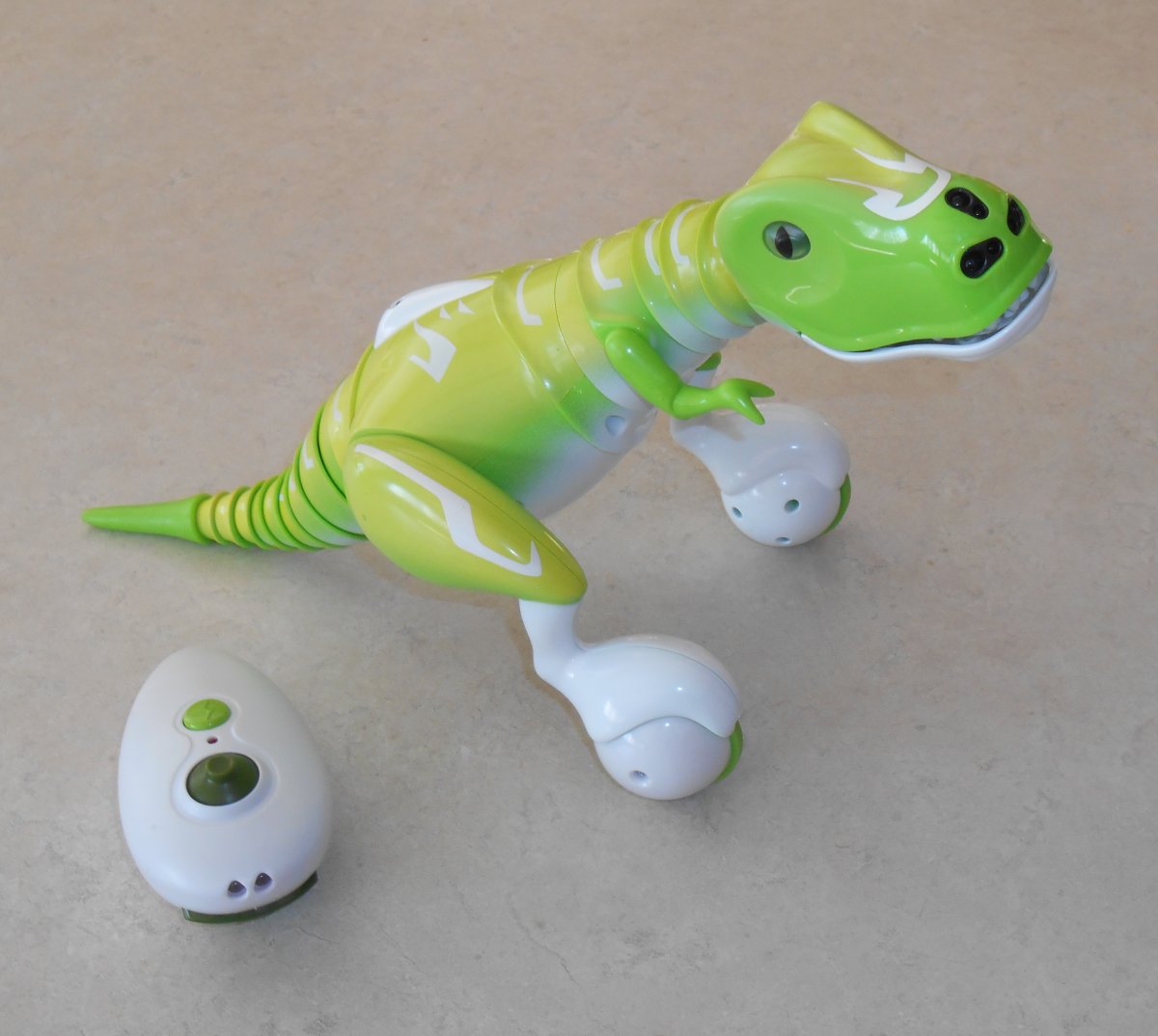
One of the hottest toys this Christmas is the Zoomer Dino. It is a remote-controlled self balancing two wheel robot dinosaur with an infrared remote. I got one for my 10-year-old nephew for Christmas and after playing around with it I had to get one of my own. I have been thinking about building Arduino powered two wheel balancing robot from scratch but here was one that works right out of the box. I’m not sure if it has a gyro or accelerometer to keep it balanced. He rolls around on his own making noises including burps, farts, and laughs. You can also take over control with an infrared remote. The remote has a joystick and three pushbuttons. The joystick moves the head up, down, left, right. If you hold in the “run” button while moving the joystick he rolls around under your control rather than moving the head. There also is a button for “chomp” which makes his jaw chomp open and closed. Additionally there is a “angry” button which makes his eyes glow red and he thrashes around angrily.
Zoomer Dino and IR remote
As with my IR controlled to a helicopter before, I had to see if I could reverse engineer the protocol it was using for the remote control. It was one of the most challenging IR reverse engineering projects I’ve ever encountered. I finally had to go out and purchase one for myself because I had to wrap up the original one for my nephew.
I used my IRLib Arduino Library for decoding and encoding IR signals. Once you push a button to get things started, the remote puts out a continuous signal that is the neutral position of the joystick with no buttons pushed. I came up with a raw dump of the timing values using my IRrecvDump sample sketch. Here are the results.
This is a quite typical set of signals used by many protocols. Only the timings and number of bits are unique. We have a header that consists of about 9200 mark and 4800 space followed by 25 data bits and a closing mark. The data marks run about 500 or 550. The data spaces are either about 650 or 1800. This variable spacing is the most common way to encode zeros and ones. We’ll call the short spaces ones and the long spaces as ones. I created a custom decoder object as follows.
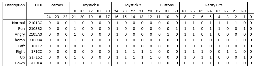
Because the remote sends signals continuously, this routine only reports the initially received value and then anytime the value changes to something different. It outputs 6 hex digits but note that there are 25 data bits being received. I then plugged the hex values into an Excel spreadsheet, converted them to decimal, and then parsed out the individual bits to try to deduce a bit pattern. I tried leaving the joystick alone when pushing the 3 buttons individually. Then I tried moving the joystick full throw forward, backwards, left, and right. The results are shown in the table below. You may click the table image to enlarge it.
Table 1-Bit patterns from Dino remote.
In all samples, the first three bits were always zero as was the last bit. It was pretty obvious that after the initial zero bits, there was a five bit field that was the left/right position of the joystick with the left position having a value of zero, the center as 16, and the right was 31. This was followed by another five bit field that was the forward/backwards joystick position with zero to the back, 16 in the center and 31 full forward. The next three bits were obviously the three buttons. There were eight additional bits that seem to have no rhyme or reason to them.
Here is a revised version of the receiving code that parses out the bits into their individual fields.
void setup()
{
Previous=0;
Serial.begin(9600);while (! Serial);delay(1000);
Serial.println(F("Send a code from your dino remote and we will decode it."));
My_Receiver.enableIRIn(); // Start the receiver
}
void loop() {
if (My_Receiver.GetResults(&My_Decoder)) {
My_Decoder.decode();
if(My_Decoder.decode_type == DINO) {
if(My_Decoder.value!=Previous) My_Decoder.DumpResults();
Previous= My_Decoder.value;
}
else Serial.println("Unknown");
My_Receiver.resume();
}
}
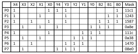
But what to do about those parity bits? I had to presume they were some sort of checksum or other data verification field. Normally when capturing and decoding IR signals I really don’t care what the data represents internally. I point a TV remote at my receiver circuit, capture the hex value, and then re-create that value using my IR transmitter. I could have just quit now and build an application on the Arduino that would transmit button pushes and fixed joystick positions but it would be nice to be able to use any joystick position that I wanted from 0- 31 in either X or Y directions in any combination. But to do that I needed to figure out how to compute those additional eight bits of data.
Most consumer-electronics protocols use a simple checksum of adding the previous data fields together. Sometimes you take the 1’s complement of the data and repeat it. Sometimes you use bitwise XOR to combine the fields. I spent three days playing around with various versions of my Excel spreadsheet analyzing lots of bit patterns captured from the remote and could not deduce the pattern. I asked a couple of online acquaintances if they had any suggestions but they’re only input was to try checksum, XOR etc. A cyclical redundancy check or CRC was another option but that would be hard to reverse engineer and they generally are not used for such short streams of data. Keep in mind were only talking about 13 bits of actual data if you don’t count the leading and trailing zeros or the eight check bits.
At one point I remembered there was something called a Hamming error correction code. I had learned about them in college in my CS 484 class with Dr. Judith Gersting over 25 years ago. I barely understood how they worked back then and I’ve not used them ever since so the chances of me being able to figure it out on my own were represented by the three initial zeros in the data stream 🙂 Dr. Judith Gersting was not my only mentor in college. Her husband Dr. John Gersting told us on the first day of programming class that he was not going to teach us programming. He was going to teach us to teach ourselves programming because the minute we walked out the door, everything would probably be obsolete anyway. He literally handed us a textbook that he wrote and told us to go teach ourselves the course. I guess I was going to have to do some Google searches and teach myself everything I needed to know about Hamming codes.
As it turns out there is no one single way to create an error detecting/correcting code. There are entire websites devoted to multitudinous ways and they all use notation that I didn’t understand. I did find one website from UMass linked here.
One thing I have learned about Hamming codes was that they typically only add a vary few extra bits. Using the calculator linked above if I put in a 16-bit value it would only add five additional bits. I was getting eight additional bits on just 13 bits of data. But the one thing I did learn from that page was the way you calculate those extra parity bits. There is a matrix that tells you which of the data bits to add together to get each of the individual parity bits. I really had to do was figure out which data bits contributed to each parity bit. I had already noticed that if you push the “run button” which I have listed as “B0”, that parity bits P2,P1,P0 all inverted from their normal position. Similarly the “angry button” which is “B1” toggles parity bits P3,P2,P1. Similarly the “chomp button” labeled “B2” toggles P4,P3,P2.
So I made a new set of columns in the spreadsheet to compute the parity bits. I begin by saying…
P0=B0

P1=B0+B1

P2=B0+B1+B2

P3=B2+B1

P4=B2
Additionally the center position of the joystick had only a single bit set, the highest order bit of the five bit field which was value 16. By comparing those to the joystick positions which were all of the way left or on the way back (which consisted of all zeros) I could figure out which parity bits changed based solely on X4 and Y4. Quite by chance I also found had captured samples with X positions of exactly 8, 4, and 2. So that told me which parity bits were based upon X3, X2, X1, and X0. As I updated the formulas for calculating each parity bit, I compared the computed results to actual capture values for every hex value I’d captured. I had a list of over 30 values that I had dumped from simply wiggling the joystick around. Eventually I was able to fill in the blanks and came up with the following formulas.
Comparing my computed results to all my captured results I was convinced I had completely deduced how the parity bits were calculated. When you put those results in a table as follows, there is a definite pattern to them. It looks a lot like the patterns that had been seeing on various websites.
Table 2-Parity calculation matrix.
Finally I was able to create a sending routine that allowed me to test all of this out. This is a somewhat stripped-down version of what I ultimately came up with. You upload the sketch, call up the serial monitor, and type various characters into the monitor. The sketch then interprets those as commands and sends the proper hex code to the IR transmitter.
void IRsendDINO::send(unsigned long data) {
sendGeneric(data,DINO_BITS,DINO_HEAD_MARK, DINO_HEAD_SPACE,
DINO_ONE_MARK, DINO_ZERO_MARK,DINO_ONE_SPACE, DINO_ZERO_SPACE, 38, true, 0);
delay(27);//Average gap was 26700 us
};
void SendMultiple(unsigned long Data, char Count) {
for(char i=0;i<(Count);i++) {My_Sender.send(Data);};
};
void setup()
{
Serial.begin(9600);;delay(2000);while (! Serial);delay(2000);
Serial.println(F("Enter one of the following letters A,C,U,D,L,R,F,B,<,>,N,0"));
Normal=1;
};
void loop() {
char Cmd;
if (Serial.available()>0) {
switch (Cmd) {
case 'A': SendMultiple(0x2105a0, 9); break; //anger
case 'C': SendMultiple(0x201984, 6); break; //chomp
case 'U': SendMultiple(0x21f162, COUNT); break; //head up
case 'D': SendMultiple(0x2000ae, COUNT); break; //head down
case 'L': SendMultiple(0x010112, COUNT); break; //head left
case 'R': SendMultiple(0x3f003a, COUNT); break; //head right
case 'F': SendMultiple(0x21f36c, COUNT); break; //forward
case 'B': SendMultiple(0x2002a0, COUNT); break; //backwards
case '<': SendMultiple(0x01031c, 5); break; //spin left
case '>': SendMultiple(0x3f0234, 5); break; //spin right
case 'N': Normal=1; break; //send neutral commands
case '0': Normal=0; break;//send wiggle commands
}
} else {//if no serial data then send either normal play mode or sit still
if(Normal) {
//Un-comment next line to have Dino do normal behavior.
// My_Sender.send(0x2101bc); //Comment out to turn off continuous transmission
} else { //wiggle slightly in an attempt to set still
My_Sender.send(0x21132c);
My_Sender.send(0x20f27e);
}
}
}
The actual remote sends continuous streams of data even when you aren’t doing anything. If you don’t touch any buttons or move the joystick for about one minute it eventually shuts down. If you are not pushing a button and the joystick is in the neutral position, the dinosaur engages in various preprogrammed behaviors. I needed a way to get him to sit still while I’m typing in the next string of letters. If you select “Normal” mode. It doesn’t send any signals. If you press a “0” it continuously sends a tiny forward and backwards code which basically has him sit in one place. He wiggles a tiny bit and make some noises but he doesn’t go off on his own. Then when you type other letters he goes in the direction you want him to. You can look at the “switch statement” to see which characters perform which functions. I send multiple transmissions of each code. The default number of signals is defined in COUNT so it was easy to change the default. I have a more advanced version of the sketch which causes him to move at various speeds, shake his head repeatedly, travel in zigzag motions etc. I also added commands to make him go forward and right or forward and left simultaneously. That way he doesn’t spin in place, he turns in a broad curve. In the demo video below I use that feature to make him travel in an oval-shaped pattern.
Know that all of the driving patterns I put him through in the video below could be done with the actual remote. You’ll have to trust me that they were created using an Arduino and my software.
My ultimate goal is to port my code to my pinoccio board which includes Wi-Fi and mesh radio. That way I can control him through a webpage similar to this. I will end up with an “Internet of things” remote control dinosaur. The pinoccio has a LiPo battery and is very small. I might just velcro it with an IR LED to the back of the dinosaur and not worry about maintaining a line of sight from my transmitter. I will post more details when and if I ever get that working.
Here is where I demonstrated the project on the Adafruit weekly Show-and-Tell on Google Plus Hangouts.
We are pleased to announce that IRLib has been updated to version 1.5. IRLib is a library for Arduino-based microcontrollers that allows for the receiving, decoding, and sending of infrared signals. These new changes are a step forward in making the library less hardware platform dependent so that it can be more easily used by a variety of microcontrollers. These changes include…
New bit-bang option for PWM output frequency setting. Now can use any output pin with no hardware timers. Note:bit-bang output not as accurate as timer-based frequency selection.
Major rewrite of IRLibTimer.h to facilitate bit-bang. Separated hardware timer selection and specification into sending and receiving sections in order to implement bit-bang.
New IRfrequency class for detecting input frequencies. Previously was a stand-alone special sketch but now is a class including a DumpResults method.
New IRfreq and IRrecvDumpFreq illustrate simultaneous detection of frequency and pattern with both an IR learner and IR receiver is connected.
New #define USE_IRRECV define can be commented out to completely remove the interrupt driven IRrecv receiver class from the library. This resolves ISR conflicts with other libraries such as Tone() when not using IRrecv class.
New #define USE_DUMP define can be commented out to disable DumpResults methods. Saves code space when these methods are not needed.
Revised user manuals to document new features and correct previous documentation problems.
Note: The included user manual update is not yet available on the website at http://tech.cyborg5.com/irlib/docs/ but it will be updated shortly. New user manual is available with the library itself as a Microsoft Word .docx file as well as PDF and EPUB versions.
This library is available on GitHub at . For more information on this library see http://tech.cyborg5.com/irlib/
Here is a YouTube video demonstrating how I created an internet of infrared remote using the new Pinoccio platform. The Pinoccio is an Arduino compatible board based on the ATmega256RFR2 chip. It uses a Wi-Fi backpacked and built-in 802.15.4 mesh radio.
As mentioned in the video I have not yet released my source code for the Pinoccio port of my IRLib but I will do so very soon.The source code is now available on GitHub here. Read more about Pinoccio (and yes it really is spelled without an “h”) at https://pinocc.io. And my IRLib at http://tech.cyborg5.com/irlib/
Update: I also did a live demonstration of this project on the Adafruit Industries Google+ Hangout weekly Show-and-Tell which you can see here…
At some point I will post an extensive tutorial on this project.
My Pinocchio boards arrived today in the mail. By the way I’m going to continue to call them Pinocchio rather than it to spelling Pinoccio simply because it’s easier to dictate using my voice control software wherein I do not need to go back and delete the “h” each time I type the word. For an explanation of the name you can see their FAQ here.
This board started out as a crowdsource funded project on indiegogo.com. It was billed as “A Complete Eco-System for Building the Internet of Things”. It consists of an ATmega256RFr2 microprocessor, a USB interface, a temperature sensor, an RGB LED, and a LiPo battery. The mesh radio built into the chip is a 2.4 GHz transceiver supposedly capable of ZigBee and IEEE 802.15.4 transmission although I’ve not yet seen anything about how to communicate with X-Bee or ZigBee modules from other manufacturers.
The package I ordered as part of my funding sent me two modules, one of them with a Wi-Fi shield or backpack as they call them. They call the boards “Scouts” so the one with the Wi-Fi shield is the “Lead Scout” and those without Wi-Fi are called “Field Scouts”. As a milestone perk I also got a prototyping shield and a small USB cable for charging and configuring. Here are some photos of the devices as shipped. (Click the images for larger view.)
Everything I Got
Topside view: Lead Scout with Wi-Fi on top. Field Scout below.
Bottom view showing battery.
The units use a micro USB cable. The first one I tried was a mini USB with an adapter on it. The adapter was too large because it got in the way of the Wi-Fi shield. I finally found a cable in my pile of cables. I wanted to be able to plug in both of them at once but as it turns out that may be a bad idea.
There was a card included that says to get started I should open a chrome browser and go to hq.pinocc.io and download their chrome app. I thought about browsing around the website and reading a bunch of documentation but one of the things the designers have said is that it ought to be easy to get started. They spent a lot of time working on the software and the front end for this thing rather than just creating the hardware and sending them out. In fact the original deadline for shipping was last July and here is the following April. So I thought I would give it the acid test and play dumb and see what I can find.
The app loaded just fine and I got a screen that told me to click to add a Scout control panel. They call the control panel “HQ” The first thing it said I had to do was to downloading Windows driver and install it. They tell you to plug in the device first and then it would tell me that no driver was available. Then it suggested I go to Device Manager via Control Panel in Windows and then I would find the device under “Ports (COM & LPT)”. It was not there it was under “Other devices” which is no big deal. I downloaded the driver and unzipped it into a folder. I would’ve preferred a self extracting installer but that was no big deal. When I tried to install the driver, Windows for bid me because it was not signed. No mention of that fact in any of their documentation so minus a few points for that problem as well. This was a Windows 8.1 64 bit machine. I had had trouble loading Arduino drivers on my laptop for the same reason and I found a website that explains how to permanently turn off that feature. I don’t know why I had not had the similar problem with Arduino drivers on my desktop Windows 8.1 PC. If you are interested… here is the website that tells you how to do it. That went relatively well.
Then I went to the process of configuring the lead scout. It took me several attempts and some email exchanges with their technical support people. Eventually it did start working but I’m not really sure what we did to fix it. It seemed to me that the steps they outline history followed in an exact precise manner.
Scouts in a mesh are configured together in something called a “troop”. So the first thing you have to do is give it a troop name. I chose “The Collective” (as an homage to Star Trek’s Borg). Then you name your lead Scout. I chose “Picard”. It then searches for Wi-Fi signals and asks you which Wi-Fi it should try to connect to. You are the Wi-Fi from the list and enter your password. There’s also a manual option if it cannot detect your Wi-Fi. When you completed that a screen pops up telling you that it succeeded adding your lead Scout to the Scout HQ. It then tells you to unplug the device so that it will reset and reconnect to your Wi-Fi. After that you click on the button that says “Done”. Apparently they are very picky about the order. You cannot click done until you’ve unplug the device and give it time to reset. Even then I had difficulty getting it to work right. In the end the only reliable way I could configure it was to unplug it and turn its power switch off and on. Then wait a few seconds before clicking done. Oh by the way when you first plug it in, the HQ searches for it and tells you that he could not find the device and that you probably forgot to turn it on. But it doesn’t tell you where the switch is. It’s not obvious. Anyway after unplugging, cycling the power switch, waiting a few seconds, and then clicking the done button it seemed to work okay.
You go to the same process for the field Scout although it does not prompt you for Wi-Fi information since it doesn’t have Wi-Fi.
The HQ app gives you the ability to turn on the RGB LED and change colors. It tells you the percent your battery is charged any gives you the temperature from the temperature sensor. I took my field Scout outside to see what the outside temperature was. Unfortunately it was raining so we had to put it in a plastic bag when sitting it out on the back porch. I don’t know how accurate the temperature was but it did change to a reasonable value. There are also controls for configuring the several I/O pins. There’s also a command line for sending for sending script commands. Here are some screen grabs showing the two scouts.
HQ control panel for the lead scout “Picard”
HQ control panel for field scout “Seven-of-Nine”
There are variety of script commands that you can use on the command line. Here is a link to the reference page.
The next thing I tried to do was use the Arduino IDE. You have to download a beta version because the current IDE does not support that chip. Again is a zip file rather than an installer. I already had the current production Arduino IDE installed on this machine. I took a chance and just copied the new files over the old ones. Apparently that was not the right thing to do because when I tried to compile an example sketch I get a “compiler error” with no error message whatsoever. I will probably go back and uninstall original Arduino IDE and delete all the files and try to reinstall the beta version from scratch. But that’s a task for tomorrow.
It’s going to be a steep learning curve to do anything really useful with this. Of course my ultimate goal is to port my IRLib and use it to make an “Internet-of-Things” infrared remote. Let’s going to take lots of time with data sheets and schematics. It looks like as powerful system but are not a long way to go in order to get it to do what I wanted to do.